


IP258
41
Appendix D
D. HANDHELD COMMUNICATOR – MOBREY – CK*
D.1.0. Hand Held Communicator – Assembly Instructions
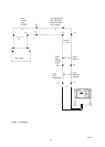
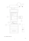
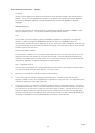
The MOBREY-CK* SMART Hand Held Communicator is supplied as a kit of items (Figure DI) which are
assembled as follows:
D.1.1 Remove the lower sliding cover (1) of the Psion organiser (2) completely to expose the battery compartment lid
(3) at the base of the keypad, and the two slots for Datapaks behind the right hand side of the keypad.
D.1.2 Remove the lower of the two blank Datapak mouldings and insert the preprogrammed Mobrey SMART Datapak
(4), pressing the unit home. This lower slot is the “C” slot in Psion Organiser memory.
D.1.3 Remove the battery compartment lid (3) and insert the 9V battery (5), positive terminal first. Replace the
battery compartment lid (3) and the lower sliding cover (1) over the base of the Psion Organiser. Leave the
keyboard exposed.
D.1.4 At the top of the Psion Organiser above the LCD, slide the cover across to the right to expose the connector.
Insert the MOBREY SMART interface unit (6) in this slot.
D.1.5 The lead used to connect the MSM400 cabling is plugged into the MOBREY SMART interface unit. On the
MOBREY-CK1 and MOBREY-CK3 this is via a 3.5mm jack plug. On the -CK2 a multi pin plug is used. The
latter also has the hook-on connectors built into the leads instead of push on crocodile clips.
D.1.6 The MOBREY SMART Interface Unit has another socket at the top left hand side for connection of a standard
Psion external power unit as an alternative to battery operation.
D.2.0. Notes
D.2.1 Although it is possible to insert two Datapaks into the HHC, this is not recommended as a conflict between
them can occur.
D.2.2 The MOBREY-CK* Datapaks enable communication with both MSP100 ultrasonic level transmitters and
MSM400 displacement level transmitters, and also gives generic support for all other HART transmitters.
D.2.3 When not in use, remove the Mobrey SMART Interface unit from the HHC to prolong battery life.
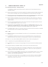
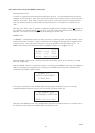
D.3.0. Requirements for loop powered SMART Operation (Refer to Fig. DII)
D.3.1 The MSM400 control unit requires a DC supply voltage of 2.5 volts at its terminals for satisfactory operation
(V3).
D.3.2 Resistance between any two SMART Interface connection points must exceed 250 ohms. (R1).
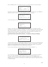
D.3.3 For the minimum DC supply voltage (V1) to be calculated, the voltage drops in the loop at 20mA must be
assessed. The absolute minimum value of V1 will therefore be 7.5 volts, since 5 volts is required for the
voltage drop across R1 at 20mA. (See Note 2 below).
D.3.4 If R1 is 250 ohms or more the SMART communicator can be connected between B1-B2, or C1-C2, or D1-D2
or E1-E2. It is also allowable to connect across the SMART Load resistor R1, on B1-A1, or across any
resistance in the circuit that exceeds 250 ohms.
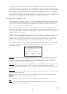
D.3.5 The current loop load resistance R2 can be considered to be part of the 250 ohms needed as the SMART
Load resistor. In this case R1 + R2 must exceed 250 ohms, and the communicator can be connected
between C1-C2, D1-D2, E1-E2, or C1-A1.