


IP258
39
2.0 SMART COMMUNICATION WITH THE MOBREY MSM400
With a SMART HHC, you can make adjustments and calibrate your MSM400 at any point on the two wire
connection to the control unit. You can also make many other adjustments and obtain operational and
diagnostic information using the HHC.
Alternatively, Mobrey have a PC based software package called Mobrey H-View which allows you to make
adjustments and obtain readings through a standard PC. Contact Mobrey or your local agent for details.
If you have a Mobrey type CK HHC (Psion Organiser based) and the appropriate datapak, refer now to
Appendix D for details of assembly, connection and menu structure before reading on to the specific
adjustments listed below.
If you have another type of SMART communicator or computer based software tool, you must ensure that the
MSM400 Device Description (DD) is correctly loaded or compiled to gain access to all of the MLT parameters.
If you do not have the MSM400 DD loaded, you will only be able to access the Universal and Common
Practice commands.
Contact or any other HART Host Subscriber to update your communication device with the latest MSM400
DD.
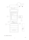
The MSM400 control unit is a SMART instrument using the HART protocol to communicate with external
devices.
The Mobrey HHC is a hand-held organiser based communication device fitted with a HART interface to allow
communication with Mobrey HART instruments.
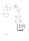
By connecting the HHC across the two wire loop at any point downstream of the minimum 250 Ohm loop
resistance, communication can be established. The MSM400 has integral test pins provided for this purpose.
Refer to Appendix D3.0 for details of HHC connection and operation.
The following paragraph details how to re-range and change damping using the HHC once communication
with the MSM400 has been established.
2.1 Calibration adjustments at operating conditions.
Important note : Making changes to the position or span of the 4-20mA range with a communicator can cause
the control unit to make step changes in the output. You should arrange to set your plant control loop to
“Manual” before making changes if this could be a problem.
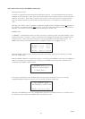
4mA point – from the “Program” menu / “Calibrate” sub-menu, access Parameter P500. The factory default
value is “0”.
Enter the desired new value of the PV (Process Value), normally the sludge level in % solids, required to give a
4mA output, and confirm when prompted by pressing the “exe” key that this is correct. The new value is now
entered and saved.
Note, the 4mA point can be positioned above the 20mA point to reverse the operation of the control unit,
thus giving a falling current output with rising sludge level.
20mA point – from the “Program” menu / “Calibrate” sub-menu, access Parameter P501. The factory default
value is “A”. This represents “Automatic” and in this case means that the 20mA point is automatically set to
the maximum range of the control unit.
Enter the desired new value of the PV (Process Value), required to give a 20mA output, and confirm when
prompted by pressing the “exe” key that this is correct. The new value is now entered and saved.
Damping – from the “Program” menu / “Engineer” sub-menu, access parameter P625. The factory default
value is 5s.
Enter the desired new value in seconds and press “exe” to confirm and save the new value.