


WARNING – SERVICING TO BE CARRIED OUT ONLY BY AN AUTHORISED PERSON
Disconnect from electricity before servicing. Check appliance is safe when you have finished.
22
7. Servicing
Disconnect the cooker from the electricity supply
before servicing, particularly before removing any
of the following: control panel, side panels, ceramic
hob, or any of the electrical components or cover
boxes.
Before reconnection, check that the appliance is
electrically safe.
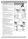
1. To Remove a Side Panel
Disconnect from electricity supply.
Pull the cooker forward. Remove the fixing screws.
Remove the retaining screws for each panel (one at the front,
two at the rear, and one at each lower front corner of the side
panels).
Reassemble in reverse order.
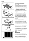
2. To Lift up the Ceramic Hob
Disconnect from electricity supply.
Remove the blanking plugs at the top front of each of the side
panels to allow access to the hob fixing screws (1 each side) at
the top of the side uprights. Remove these screws.
Lift up the ceramic hob at the front and prop in position with a
non-metallic prop.
CAUTION: The ceramic hob material is much more sensitive
to scratches on the underside than the top.
Take care not to touch or scratch the underside of the ceramic
as this will weaken the material and cause the top to shatter.
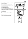
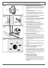
3. To Remove the Control Panel
Disconnect from electricity supply.
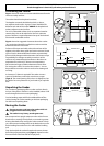
Remove the two blanking plugs from the handrail fixing
brackets. Remove the handrail by unscrewing the 2 end
bracket fixing screws (Fig.7-1).
Pull off all the control knobs. Open the grill and right-hand
oven door and remove the control panel fixing screws
underneath the control panel. The screws directly below the
clock are for the clock fixing bracket, so do not remove them
at this stage.
Lift the control panel, pull forward and disconnect the wiring
from the rear.
Reassemble in reverse order. When replacing leads, refer to
the wiring diagram in this manual. Check the operation of the
timer.
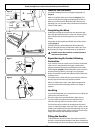
4. To Replace a Hob Element
Disconnect from electricity supply.
Lift up the ceramic hob (see 2). The Induction Heating
Elements (IHE) are now accessible. Note the wire connection
positions and element orientation for re-assembly. Disconnect
the wires, and remove the element unit and springs. Re-
assemble in the reverse order.
Note: The IHE will require commissioning when the hob has
been refitted.
5. To Replace the Light Switch
Disconnect from electricity supply.
Remove the control panel (see 1).
Note: The old switch may be destroyed during removal.
Remove the old switch from its bezel by gripping the switch
body behind the control panel and twisting sharply. Remove
the switch bezel by folding back its locking wings and pushing
forward. Fit the new bezel to the control panel by first lining
up the raised key on its body with the cut-out in the control
panel and pushing it in from the front.
Assemble the new switch to the bezel by lining up the key
sections and pushing home. Fit the new button by pushing in
from the front.
Replace the Control Panel in reverse order and test for correct
operation.
6. To Remove the Electronic Timer
Disconnect from electricity supply.
Remove the control panel (see 1). Pull off the timer control
button(s).
Remove the timer/mounting bracket assembly from the
control panel by removing the fixing screws.
Remove the timer from its mounting bracket by depressing
the plastic lugs on the timer case, at the same time pulling the
unit forward.
Reassemble in reverse order. When replacing the leads, refer
to the wiring diagram in this manual. Check the operation of
the timer.
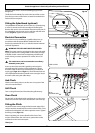
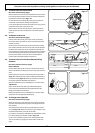
7. To Replace a Thermostat
Disconnect from the electricity supply.
Remove control panel (see 1) and lift hob (see 3). Open the
oven door. Remove the oven furniture and slide out the oven
roof liner if fitted.
For the right-hand oven, remove the thermostat phial cover
(two screws). Unclip the thermostat phial from the clips in the
oven back.
For the left-hand oven, pull cooker forward to gain access
to the cover box at the rear of the cooker. Remove the four
screws securing the cover and lift clear.
Feed the thermostat capillary out of the oven. Disconnect
the wiring from the thermostat. Remove two screws holding
thermostat to mounting panel. Fit new thermostat and
reassemble in reverse order. Ensure that the phial is clipped to
the oven back with the phial centrally positioned between the
clips.
Check the operation of the thermostat.
8. To Replace the Grill Controller
Disconnect from electricity supply.
Remove the control panel and lift up the hob (see 1 and 3).
Disconnect the wiring from the controller. Remove the two
screws holding the controller to the mounting panel. Fit the
new controller and reassemble in reverse order. Check for
correct operation.
DocNo.081-0013GB - Servicing - 90 induction - Elan