


Page 4
PROCEDURE FOR CALCULATING TOTAL EQUIVALENT PIPE LENGTH IN FEET
1. Calculate the total equivalent feet for each type of fitting used in the venting system from the chart below.
2. Calculate the total amount of feet for the straight lengths of vent pipe.
3. Add the equivalent feet for the fitting with the total amount of feet of straight lengths. This will approximate the total
equivalent feet of the vent system.
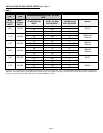
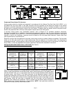
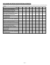
Table 2
EQUIVALENT LENGTH (FEET) OF VENT PIPE FOR VENT PIPE FITTING
VENT PIPE DIAMETER
VENT PIPE FITTINGS
3” 4” 5” 6” 7” 8” 9” 10”
TEE
19 25 31 38 44 50 56 63
90° ELBOW
5 7 9 11 12 14 16 18
45° ELBOW
3 4 4 5 6 7 8 9
d/D
1/4 8 11 14 17 19 22 25 28
1/2 5 7 8 10 12 13 15 17
SUDDEN REDUCER
OR INCREASER
FOR 3 *RATIOS (d/D)
3/4 2 3 3 4 4 5 6 6
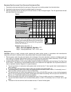
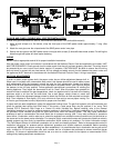
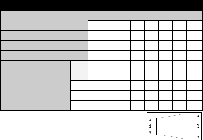
*Reducer or increaser ratio (d/D) small diameter divided reducer
ratio is d/D = 4/8 = 1/2. To estimate the equivalent foot length for
the fitting, use the smaller pipe diameter for the equivalent length
figure. Example 4" to 8" reducer; the reducer ratio is 1/2 and the
smaller pipe diameter is 4". So, from the chart, the equivalent feet
would be 7 feet. (See Figure 1)
Example: System Pipe Size = 4"
Step 1 Two 4" 90° elbows @ 7 feet each = 14 ft.
Step 2 Ten 2 foot lengths of 4" pipe = 20 ft.
Step 3 Total equivalent feet = 14 ft. + 20 ft. = 34 ft.
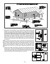
INSTALLATION
CAUTION: Failure to install, maintain and/or operate the power venting system in accordance with manufacturer's
instructions will result in conditions which may produce bodily injury and/or property damage.
1. Remove power venter from box and inspect unit for damage. If the carton has been crushed or mutilated, check unit
very carefully for damage. Rotate blower wheel to insure that the motor and blower wheel rotate freely. DO NOT install
if any damage is apparent. Refer to unit sizing chart to check proper venting sizing.
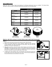
2. Location of the termination of the venting system should be installed in accordance with the National Fuel Gas Code
A.N.S.I.Z223.1, manufacturer's recommendations and/or local codes which are applicable. See requirements below or
refer to installation location, Diagram A, for typical locations.
a. The exit termination of mechanical draft systems shall not be less than 7' above grade when located adjacent to
public walkways.
b. A venting system shall terminate at least 3' above any forced air inlet located within 10'.
c. The venting system of other than a direct vent appliance shall terminate at least 4' below, 4' horizontally from or 1'
above any door, window or gravity air inlet into the building.
d. The vent termination of a direct vent appliance with an input of 50,000 BTU's per hour or less, shall be located at
least 9" from any opening through which vented gases could enter the building. With an input over 50,000 BTU's
per hour, a 12" termination clearance shall be required.
e. The vent termination point shall not be installed closer than 3' from an inside corner of an L-shaped structure.
f. The vent termination should not be mounted directly above, or within 3' horizontally from an oil tank vent or gas
meter.
g. The bottom of the vent terminal shall be located at least 12" above finished grade.
Figure 1