


Page 6
Figure 5
CONNECTING POWER VENTER TO APPLIANCE
Venting system should be installed and supported in accordance with the National Flue Gas Code A.N.S.I.Z223.1, or in
accordance with any local codes. A vent pipe connector shall be supported for the design and weight of the material
employed, to maintain clearances, prevent physical damage and separation of joints. A vent pipe increaser or reducer may
be required for connecting the power venter to the vent system. If needed, place the reducer close to the power venter.
Smaller vent pipe sizes than a chimney-vented system may be used for the vent system.
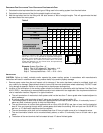
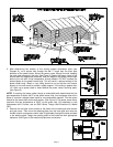
If mounting venting system near combustible materials, refer to Diagram B for allowable installation clearances.
Clearances are based on an installation using single wall galvanized steel vent pipe. For metal thickness of galvanized
steel pipe connectors, refer to NFPA 211 or NFPA 54 Standards for guidelines. If manufactured double wall vent pipe is
required or used for the installation, clearance should be based on the vent pipes rated clearance. Always check local
code requirements for code restrictions.
Route the vent pipe from the appliance to the power venter using a minimum number of elbows as possible. The horizontal
section of the vent pipe should have a slight upward slope from the appliance to the power venter. For clearances to
combustible materials, multiple appliance venting and other installation requirements, refer to the National Fuel Gas Code
A.N.S.I.Z223.1, and/or any applicable local codes or appliance manufacturer's installation instructions.
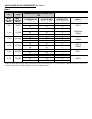
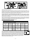
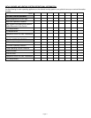
INSTALLATION USING SINGLE WALL VENT PIPE (See Table 3)
Table 3
INSTALLATION CLEARANCE WITH SINGLE WALL VENT PIPE
DOUBLE PIPE SYSTEM SINGLE PIPE SYSTEM
Allowable inlet
temperature
SWG Stainless
Steel
Allowable inlet
temperature
SWG/SWGII
Clearance
(A)
Allowable inlet
temperature
SWG Stainless
Steel
Allowable inlet
temperature
SWG/SWGII
Clearance
(B)
400°F or less 400°F or less
1/2”
minimum
400°F or less 400°F or less
3”
minimum
400°F to
650°F US/575°F CA
400°F to 550°F
1”
minimum
400°F to
650°F US/575°F CA
400°F to 550°F
4”
minimum
400°F to
650°F US/575°F CA
400°F to 550°F
1/2”
minimum
with sheet
metal liner
400°F to
650°F US/575°F CA
400°F to 550°F
3”
minimum
with sheet
metal liner
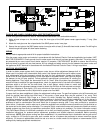
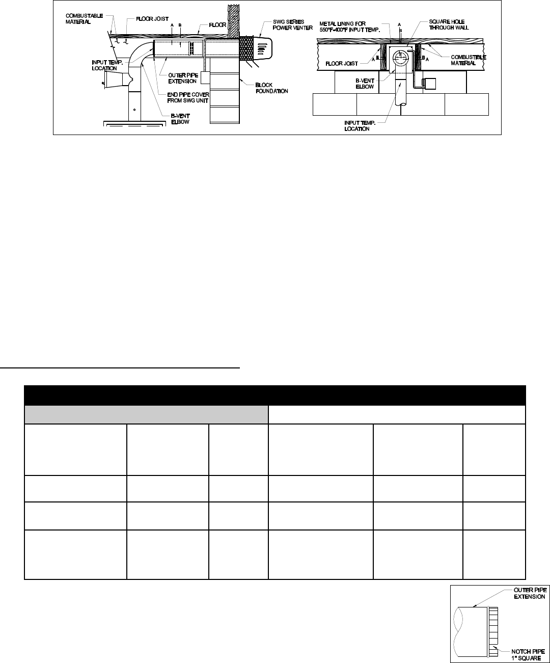
Use a PEK series extension kit or follow installation method below for a double pipe system. To
install an outer pipe extension to the SWG power venter, the end pipe cover on the power venter
must be removed. Then, cut a 1-inch square notch into the vent pipe extension before attaching
the power venter. (See Figure 5) This allows clearance for the adjustment damper. Install the
needed pipe extensions and terminate the outer pipe extension with the end pipe cover (see
Diagram B). The table above shows minimum allowable clearances when using single or double
pipe systems. When the outer pipe is extended over the inner pipe, use the double pipe
guidelines when determining clearances. Figure 6 shows how the airflow pattern through an
SWG reduces the required clearances to combustibles. NOTE: Vent pipe joints should be
secured with at least (3) three sheet metal screws.
Diagram B