


Page 7
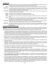
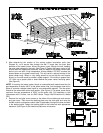
Figure 6
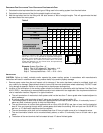
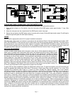
Figure 7
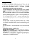
Figure 8
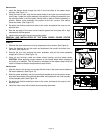
CLASS B AND CLASS L DOUBLE WALL VENT PIPE INSTALLATION
(Follow vent pipe manufacturer's listed or recommended clearances from combustible material)
1. Using a hand crimper or a like device, crimp the inner pipe of the SWG power venter approximately 1" long. (See
Figure 7)
2. Attach the vent pipe over the crimped end of the SWG power venter inner pipe.
3. Secure the vent pipe to the SWG power venter inner pipe with at least (3) three #8 sheet metal screws. Pre-drilling the
holes through both pipes will allow easier fastening.
WIRING
NOTE: Refer to appropriate control kit for proper installation instructions.
Wire the power venter motor and controls in accordance with the National Electric Code and applicable local codes. UNIT
MUST BE GROUNDED. Check ground circuit to make certain that the unit has been properly grounded. The wiring should
be protected by an over-current circuit device rated at 15 amperes. CAUTION MUST be taken to ensure that the wiring
does not come in contact with any heat source. All line voltage and safety control circuits, between the power venter and
the appliance, MUST be wired in accordance with the National Electrical Code for Class 1 wiring or equivalent.
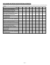
AIR FLOW ADJUSTMENTS
In order to obtain proper system draft, the power venter has an airflow adjustment damper built in.
When used in a system with a barometric draft control, this damper should be used to make coarse
draft adjustments while the barometric should be used for finer adjustments. Loosen the locking
screw on the air flow adjustment damper on the outer pipe of the power venter. (See Figure 8) Adjust
the damper to the full open position. Follow appliance manufacturer's procedures for starting the
heating appliance. Then adjust the thermostat to call for "Heat". After the system has operated for
several minutes to stabilize flue gas temperatures, check for negative draft or up-draft at the heating
appliance outlet or air flow into the draft hood. Use a draft gauge, velocity meter or match test
procedure. Adjust the adjustment damper closed to obtain the minimum air flow required to maintain
draft. Then increase air flow slightly (10% over minimum air flow rate) to ensure proper venting. For
oil-fired or gas-fired power burners, adjust draft to proper over-fired draft.
If proper draft has been established, tighten the adjustment locking screw. For gas-fired systems, shut off thermostat and
check for residual heat spilling from draft hood. If this occurs, a post purge timer may be required. If so, use a Field
Controls PPC-5 Electronic Post Purge or a Control Kit which includes one. Before installing, refer to the General
Installation Inspection to check for negative pressure problems in the building. If sufficient combustion air for the burner is
not provided, a flow reversal during the off cycle could occur within the venting system. This may cause combustion
problems as well as condensation that could block the air pressure sensing tube. It may also contribute to premature
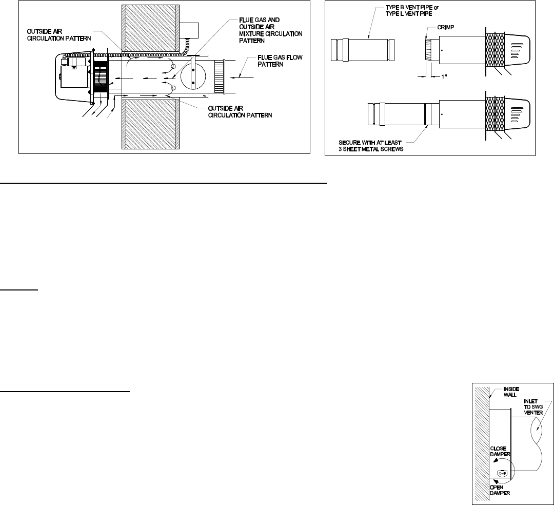
motor failure. Combustion, and/or make-up air, should be supplied from outside the structure and the air inlet should be on
the same wall as the power venter discharge. For example, tightly constructed homes and homes retro-fitted from electric
heated systems are more likely to experience combustion and/or make-up air problems. For further information consult
"The Field Report-Effects of insufficient combustion air on draft and heating systems". Refer to the appropriate control kit
installation instructions for pressure switch adjustment procedure and system checkout procedures before operating
continuously. NOTE: After proper venting has been established, it is recommended that a combustion test on gas and oil
units, a check for CO levels on gas units, and a smoke test on oil systems be performed to ensure maximum burner
efficiency. Oil burner air adjustments should be set at a zero to a trace smoke at the highest or recommended CO
2
%
setting set by heating equipment manufacturer.