


Page 5
Figure 2
Figure 3
Figure 4
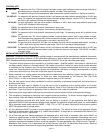
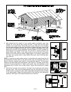
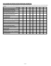
3. After determining the location of the venting system termination point (see
Diagram A), cut a square hole through the wall 1" larger than the outer pipe
diameter of the power venter. Mount the power venter through the wall, keeping
the outer pipe centered in the hole. (See Figure 3) Fasten the power venter to the
outside wall with appropriate fasteners. Seal the edges of the power venter base
plate to the wall with a high temperature silicone sealant. DO NOT enclose the
spaced plates on the power venter body. This will result in reduced cooling of the
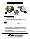
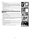
power venter body. Wood or vinyl siding should be cut so that the unit mounts
directly on the wall board to provide a stable support. If the siding is greater than
1/2" thick use a spacer plate or board behind the power venter mounting plate.
(See Figure 2)
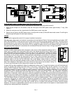
NOTE: If mounting the power venter though a combustible wall material and the flue
gas temperature is above 400°F at the power venter inlet, line the square hole with a
piece of corrosion resistant sheet metal or non-combustible material. The liner piece
should be the same width as the wall section. (See Figure 3) The power venter has a
maximum flue gas temperature of 550°F at the venter inlet. For installation in wall
thicknesses over 8 inches, use an SWG Series Though Wall Extension Kit, Model
PEK.
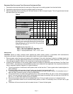
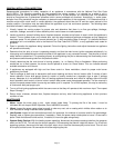
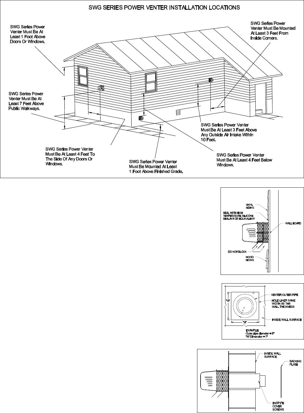
2. Remove the end pipe cover screws on the sides of the outside pipe and remove
end pipe cover. Then mount the backing plate over the outer pipe and route the
flexible conduit and pressure switch tube (if applicable) through the holes provided
in the backing plate. Fasten the backing plate to the inside wall with appropriate
fasteners. (See Figure 4) Re-install end pipe cover and screws.
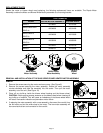
Diagram A