


Page DD_10
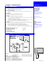
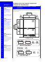
The DishDrawer should
not support any part of
the kitchen cabinets.
WARNING
The DishDrawer must be
levelled so that each
corner is at least within
1
/
8
(3mm) of level.
IMPORTANT
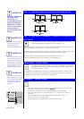
TIP
Each turn of the foot
adjusts by
3
/
64
(1.25mm).
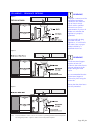
For ease when sliding the
feet back, place a little
soap on the Slide
Runners.
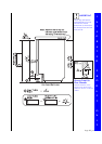
Make sure the Inlet and
Drain Hoses are not
restricted or damaged.
TIP
IMPORTANT
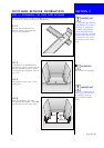
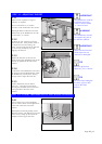
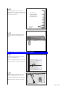
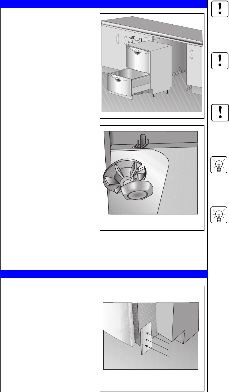
STEP 3.3 ADJUSTING THE FEET
3.3.1
Measure front of product to align to
cabinetry as required.
Ensure a minimum of
1
/
8
" (2.5mm)
clearance to the underside of the counter.
The height difference between the front
and the back of the DishDrawer must be
no more than
1
/
8
" (2.5mm).
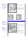
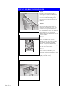
3.3.2
To adjust the feet, loosen the locknuts
and turn the feet. If the product needs to
be adjusted to its lowest setting, the
plastic surround will need to be removed
by unscrewing and lifting it up and
slipping it off the foot.
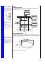
3.3.3
Tighten the locknuts on the rear feet
while ensuring the moulded section of the
feet line up parallel to the sides of the
product.
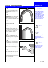
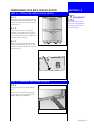
3.3.4
Lift the back of the DishDrawer and insert
the back feet into the Slide Runners. Slide
the DishDrawer partially back, leaving
enough room to adjust the front feet.
3.3.5
Further adjustment may be made if
necessary. Lock the front feet while
ensuring the moulded section of the feet
line up parallel to the sides of the
product.
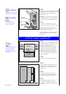
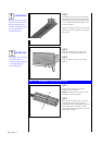
STEP 3.4 FITTING THE ENDPLATE TO THE CHASSIS (OPTIONAL)
3.4.1
If the customer sees a need, Endplates
may be used to obtain a flush appearance
to the side of Toe Kick area of the
product.
The Endplate is fitted by peeling off the
adhesive backing and adhering to the side
of the chassis, lining up the front of the
Endplate with the Upper Toe Kick.