


11
Installation instructions
Installation instructions:
1
Ensure the refrigerator is NOT plugged into a powersupply.
2
Locate a cold water supply/feed only suitable for a water
connection. Tee and tap fitting is not supplied.
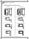
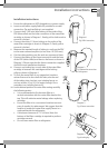
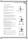
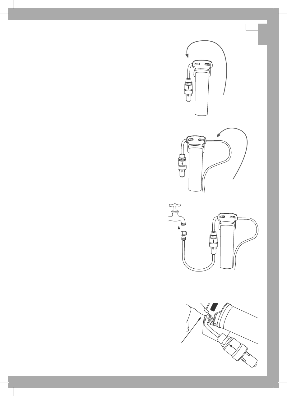
3
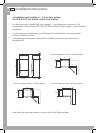
Connect the 8” (200 mm) blue tubing to the outlet of the
PRV (blue collet) and the inlet connection of the water filter
cartridge as shown in Diagram 1. Gently pull on both ends to
ensure it is locked.
4
Connect the white ¼” (6 mm) tubing to the outlet of the
water filter cartridge as shown in Diagram 2. Gently pull to
ensure it is locked.
5
Measure the required length of tubing to run from the PRV
to the water connection point (no less than 10” (250 mm)).
6
Cut the tubing making sure the ends are square and clean.
7
Connect the tubing to the faucet connection and the base
of the PRV (white collet) and then to the faucet as shown in
Diagram 3. Please note that the faucet connection supplied
should fit most installation situations.
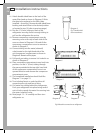
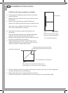
8
Connect one locking key to each side of the water filter
cartridge in between the cartridge and the locking
collet as shown in Diagram 4.
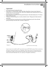
9
To flush the water filter of any trapped air, harmless
carbon fines and to also check for leaks, aim the end
of the tubing into a bucket, turn isolating faucet on
and run at least 10 qt (10 L) of water through. Once
complete, turn isolating faucet off.
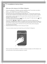
10
Locate desired position for water filter noting carefully
the following points:
It is recommended to fit the water filter in a
vertical orientation with the water filter head at the
top. This will minimize water leakage when replacing
cartridge.
Ensure the filter is in a convenient location to access
every 6 months for replacement. We suggest that this
location is beside the water filter supply faucet in a
cupboard beside the refrigerator.
A minimum clearance of 2 ½” (64 mm) from the
bottom of the filter cartridge is required to perform
cartridgeremoval.
Do not screw water filter to refrigerator.
Diagram 2
Fig.4 Waterline connection
to refrigerator
INLET
Diagram 4
Fig.6 Locking key
Fig.3 PRV connection
Diagram 1
Diagram 3
Fig.5 Faucet connection
US
CA