


19
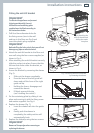
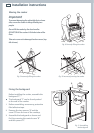
Installation instructions
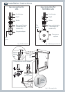
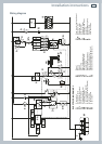
Wiring diagram
ELECTRIC DIAGRAM KEY
F1 Oven switch
ST Safety thermostat
STL Safety thermal overload
TL Thermal overload
PR Electronic programmer
PB Temperature probe
TS Oven temperature selector
EC Oven function selector (encoder)
SF State functions
DL Door lock device
DS Door sensor
R1 Relay 1
R2 Relay 2
R3 Relay 3
LF Oven lamp
TR Oven lamps transformer
S1 Door lock indicator lamp
S2 Line pilot lamp
C Oven top heating element
G Oven grill heating element
SI Oven bottom heating element (int.)
SE Oven bottom heating element (ext.)
CI Oven circular heating element
DLM Door lock motor
GIR Rotisserie motor
V Oven fan motor
CF Cooling fan motor
RS Resistance (220 Ohm)
IC Gas igniter
IS Ignition switches group
M Terminal block
T Earth connection
R1
R
R
R2
R3
X1
PR
EC
P4
PB
PHV
SF
TS
X0
LF
TR
LF
V
GIR
CF
P7
P6
P11
11
11a
12
12a
13
13a
14
14a
15
15a
P8
P9
PT1
PT2
5a
5
16
16a
6a
6
2
2a
1
1a
A
B
1
2
46
79
7a
7
8a
8
4
4a
3
3a
1
1
2
2
4
9
9a
IS
F1
F1
F1
F1
F1
F1
F1
F1
S2
S1
DLM
RS
TL
STL
ST
IC
42
M
T
PR
DL
DS
PR
PR
G
SI
SE
CI
C