


1-5
1.3.3 Adjusting the Pilot Flame
1. On non-CE valves, remove the cap covering the pilot adjustment screw. On all valves, use a at-
tipped screwdriver to turn the pilot adjustment screw counterclockwise to increase the length of the
ame or clockwise to decrease the length of the ame. (Use the diagram on the previous page to
locate this screw.) Adjust the ame to a length of 1- to 1½- inches (25 to 38 mm).
2. On non-CE valves, reinstall the pilot adjustment screw cap.
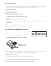
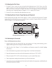
1.3.4 Adjusting Burner Ceramic Target Spacing and Alignment
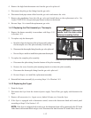
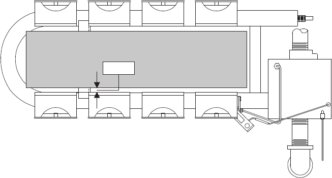
Proper spacing of the top edge of the ceramic targets is ¾-inch (13 mm) from the frypot side. To adjust
target spacing, bend the brackets away or toward the frypot, as needed. A length of board ¾-inch thick is
useful as a gauge to verify spacing and alignment.
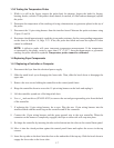
1.3.5 Calibrating the Thermostat
Fryers with thermostat access doors:
1. Fill the frypot to the lower OIL-LEVEL line with cooking oil. If using solid shortening, pack it
tightly into the frypot before starting the calibration procedure.
2. Light the pilot. (See Chapter 3 of the Installation and Operation manual for detailed lighting
instructions.)
3. Insert a thermometer or pyrometer into the frypot, about 1-inch from the thermostat.
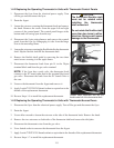
4. Open the thermostat access door and set the thermostat on the fryer to 325°F (162°C).
5. When oil reaches 325°F (162°C), allow the burners to cycle on and off three times.
6. Take a temperature reading when the burners go off for the third time.
7. Loosen the setscrews in the thermostat knob and turn the knob to the temperature established by the
thermometer/pyrometer reading.
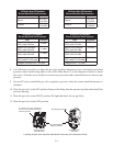
There should be approximately ¾-inch spacing between the top edge
of the targets and the side of the frypot.
¾-inch