


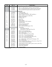

2-21
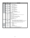
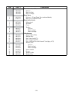
WIRING ASSEMBLIES, HARNESSES, AND REMOTE CABLE ASSEMBLIES
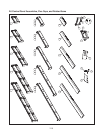
Wiring Assemblies and Harnesses
806-2079SP 100-120V Basket Lift Universal Motor (6-Pin female w/6 wires plus 1 separate wire)
806-8555SP 208-240V Modular Basket Lift Motor (6-Pin female w/6 wires plus 4 separate wires)
106-1822SP 100-120V Modular Basket Lift Motor (12-pin female w/5 wires)
106-1804SP 208-250V Modular Basket Lift Motor (12-pin female w/5 wires plus 3 separate wires)
806-4798SP Basket Lift Power, Non-CE (6-pin male w/6 wires; connects to 806-2079SP or 806-8555SP)
806-6708SP Basket Lift Power, CE (6-pin male plus 806-4798)
807-3699 Basket Lift Power, Non-CE/CE (12-pin male w/6 wires, connects to 106-1822SP or 106-1804SP)
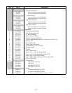
806-9777SP Thermostat Control Universal (control panel-end connections)
806-9778SP Thermostat Control Universal (component shield-end connections)
806-9779SP Basket Lift Universal (control panel-end connections)
806-9780SP Basket Lift Universal (basket lift-end connections)
806-9781SP Wiring Bundle, Component Shield to Controller and Fryer Components (21-wire bundle)
826-1560 Kit, 45 Series Wiring (contains 806-9777SP through 806-9781SP)
806-3549SP Interface Board (interface board to fryer components; 12-pin male w/5 wires)
806-6705SP CE Non-Direct Wiring Power Supply (power cords joined in junction box)
806-4214SP Fryer to Fryer Drain Safety Switch (2-pin male w/two wires and 2-pin female w/two wires)
806-4215SP Fryer to Filter Drain Safety Switch (2-pin male w/two wires and 2-pin female w/two wires)
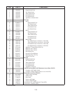
NOTE: Assemblies 806-2079SP, 806-9777SP through 806-9781SP and kit 826-1560 are “universal” in
nature. That is, they contain all wires and connectors necessary for all congurations of the application
described. Consequently, there may be “extra” wires that are not needed in a particular conguration.
Any extra wires should be removed when the assemblies are installed to preclude later confusion.
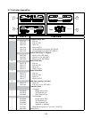
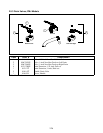
Remote Computer/Controller to Interface Board Cables
Each of these assemblies has two 15-pin male connectors, and a 15-wire cable looped through a ferrite ring.
Only the length of the cable varies.
806-2071 1.0 foot (30.5cm) (For fryer mounted computer.)
806-3383 15.0 feet (4.6m)
806-3388 20.0 feet (6.1m)
806-4318 30.0 feet (9.1m)
Remote Computer/Controller Cable Assemblies
Each of these assemblies has one 15-pin male connector, one 15-pin female connector, and a 15-wire cable.
Only the length of the cable varies.
806-3528 7.5 feet (2.3m)
806-3529 8.5 feet (2.6m)
806-3530 10.5 feet (3.2m)
806-3531 12.6 feet (3.8m)
Remote Computer/Controller Cable Assemblies w/Junction Box and Mounting Bracket
Each of these assemblies consists of a 4 X 4-inch junction box and mounting bracket assembly with one to four
15-pin female connectors and one to four 15-wire cables with a 15-pin male connector on the free end of each
cable.
806-8350 One Computer/Controller
806-8349 Two Computers/Controllers
806-8348 Three Computers/Controllers
806-8351 Four Computers/Controllers