1-8
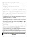
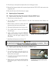
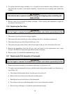
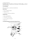
8. To replace the entire target assembly, use a ½-inch box end wrench to remove the brass orifice
that holds the assembly to the burner manifold. Position the new assembly and reinstall the
orifices.
WARNING
Use extreme care to prevent cross-threading and stripping when reinstalling the
brass orifices.
9. Reverse steps 1-8 to reinstall the burner assembly. Check spacing and alignment of targets in
accordance with Section 1.5.
1.8.6 Replacing the Gas Valve
DANGER
Drain the frypot or remove the handle from the drain valve before proceeding further.
1. Disconnect fryer from electrical and gas supplies
2. Disconnect the wires from the gas valve, marking each wire to facilitate reconnection.
3. Disconnect the pilot gas line fitting from the gas valve.
4. Disconnect the pipe union collars to the left and right of the gas valve and remove the valve.
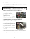
5. Remove the pipefittings from the old gas valve and install on the replacement valve, using
Loctite™ PST56765 or equivalent pipe thread sealant on threads.
6. Reverse steps 1-4 to install the replacement gas valve.
1.8.7 Replacing the Pilot Assembly or Thermopile
DANGER
Drain the frypot or remove the handle from the drain valve before proceeding further.
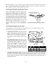
1. Remove the burner assembly in accordance with steps 1-8 of Section 1.8.5.
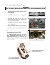
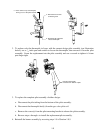
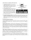
2. To replace only the thermopile in fryers with the earlier design pilot assembly (see illustration at
top of Page 1-9):
a. Disconnect the thermopile lead(s) from the gas valve pilot coil.
b. Remove the screws that secure the pilot assembly guard.
c. Bend the tab away from the base of the thermopile.
d. Press down on the top of the thermopile to force it out of the pilot assembly.
e. Reverse steps a through c to install the replacement thermopile.


