


2-6
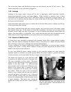
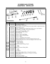
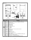
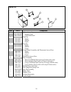
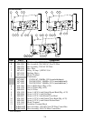
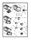
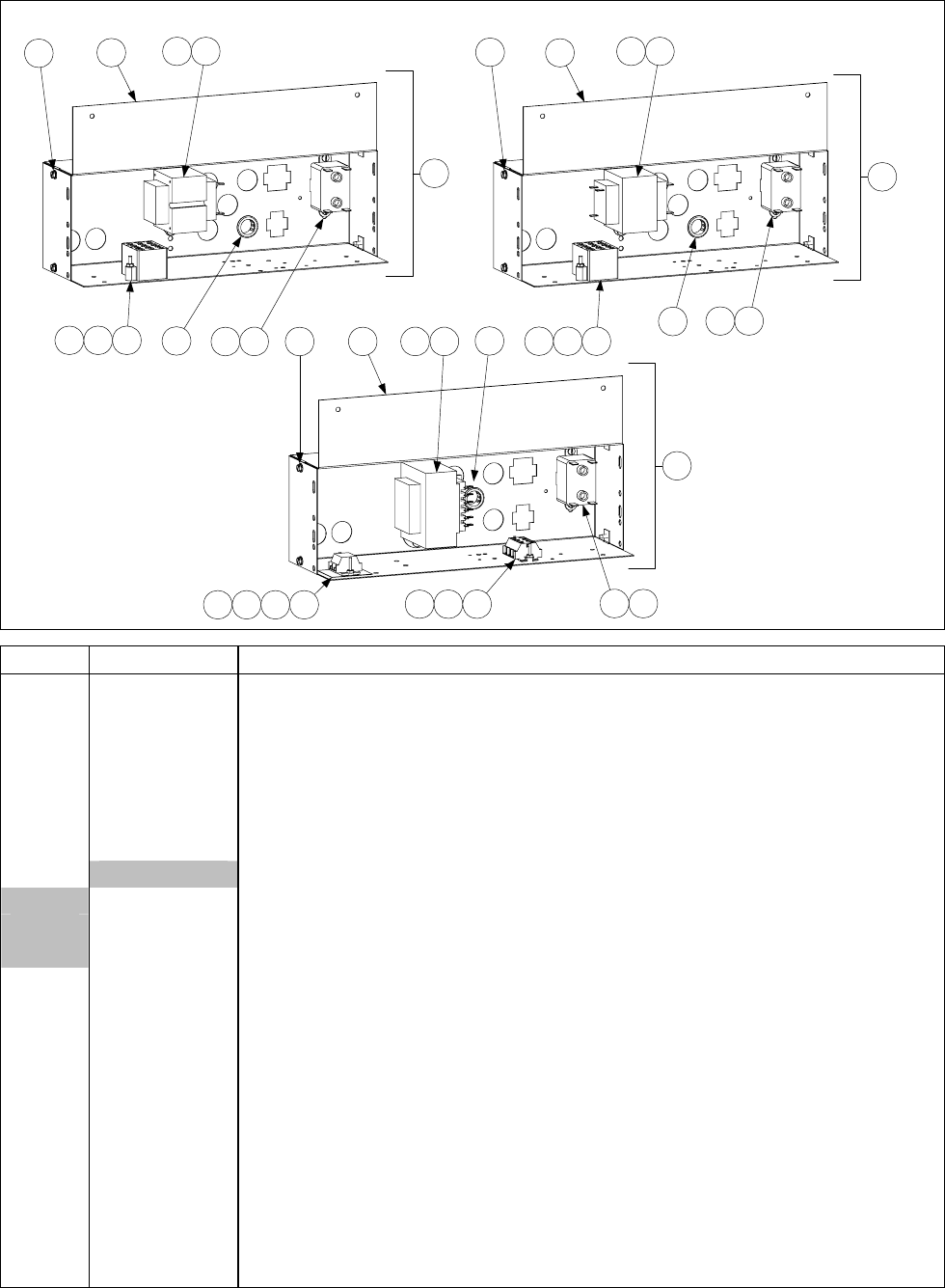
FILTER BOXES
1
1
1
82
82
2 8
3
3
3
984
984
105 105
11
11
11 105
131296
1296
A
B
C
Item Part # Component
A 806-4359SP Box Assembly, 120VAC Non-CE Filter
B 806-4360 Box Assembly, 208-240VAC Non-CE Filter
C 806-6709 Box Assembly, 230VAC CE Filter
1 200-0410 Box, Filter
2 807-0012 Relay, 18 Amp ⅓-HP 24V Coil
3 807-0124 Bushing, Heyco
4 807-0276 Block, Terminal
5 Transformer
807-0800 120/24VAC, 50/60Hz, 50VA (used with Item A)
807-0680 208-240/24VAC, 50/60Hz, 43VA (used with Item B)
807-1999 208-230/24VAC, 50/60Hz, 50VA (used with Item C)
6 826-1366 Nut, 4-40 Hex Keps (Pkg. of 25)
7 826-1358 Nut, 6-32 Hex (Pkg. of 25)
8 809-0050 Nut, 8-32 Hex
9 826-1359 Screw, 4-40 X ¾-inch Slotted Round Head (Pkg. of 25)
8 809-0096 Screw, 6-32 X ⅝-inch Slot Head
9 809-0097 Screw, 6-32 X 1-inch Slotted Truss Head
10 826-1363 Screw, 8-32 X ½-inch Slotted Truss Head (Pkg. of 25)
11 809-0360 Screw, 8-32 X ⅜-inch Slotted Washer Head
12 810-1164 Block, Terminal
13 816-0217 Insulation, Terminal Block
* WIR0010SP Wire Assembly, 120-240V Non-CE Filter Control Box
* WIR0146SP Wire Assembly, 230V CE Filter Control Box
* Not illustrated.