


6-2
guished), current to the ignition module is cut, preventing the main valve from opening, and the igni-
tion module “locks out” until the power switch is turned off and then back on.
A probe monitors the temperature in the cookpot. When the programmed setpoint temperature is
reached, resistance in the probe causes the heat cycle circuitry in the controller to cut off current
flow through the heat relay. This in turn cuts off the 24 VAC to the ignition module, causing the gas
valve to close.
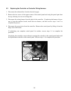
CONTROLLER AND MECHANICAL TIMERS
FBR18 and FBRA18 Series rethermalizers are equipped with a digital controller that allows the op-
erator to enter or adjust a specific rethermalizing temperature for the cookpot. The controller does
not control rethermalizing times. Rethermalizing times for up to six different products are specified
by means of 60-minute mechanical timers arrayed across the front of the unit.
INTERFACE BOARDS
An interface board is located in the component box directly behind the control panel. The interface
board provides a link between the controller and the rethermalizer’s individual components without
requiring excessive wiring, and it allows the controller to execute commands from one central point.
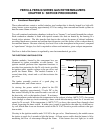
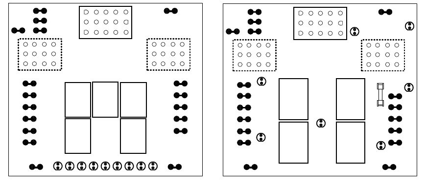
FBR18 and FBRA18 models use different interface boards. The boards are not interchangeable.
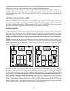
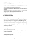
FBR18 rethermalizers have been manufactured with two different interface boards, similar in ap-
pearance to the ones illustrated below. Regardless of the board used when manufactured, the uni-
versal replacement part is 806-3398. Earlier design boards may be replaced with later design
boards and vice versa.
K4
K1 K2
SOUND
1
2
3
GND
GND
V2D
PWR
AD
AS
V2S
GND
V1D
PWR
ALR
V1S
GND GV PWR
AL 12V AIR 24V AL
PWR
GV
GND
NOT
USED
HEAT
RELAY
J2
EARLIER DESIGN INTERFACE BOARD P/N 806-3398
GND
12 6 3 45
J3
3 6 9 12
2 5 8 11
1 4 7 10
J1
3 6 9 12
2 5 8 11
1 4 7 10
15
12963
14
11852
13
10741
BLOWER
MOTOR
RELAY
NOT
USED
NOT
USED
K3 K5
K4
K1
SOUND
1
2
3
GND
GND
V2D
PWR
AD
AS
V2S
GND
GV
PWR
12V
AIR
24V
PWR
GND
V1D
PWR
ALR
V1S
GV
GND
J2
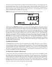
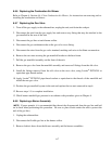
LATER DESIGN INTERFACE BOARD P/N 806-3398
GND
J3
3 6 9 12
2 5 8 11
1 4 7 10
J1
3 6 9 12
2 5 8 11
1 4 7 10
15
12963
14
11852
13
10741
K2 K3
HEAT
RELAY
AND
BLOWER
MOTOR
RELAY
NOT
USED
D1
D2
D3
D4
D6
D7
NOT
USED
NOT
USED
Blower
Motor
2 Amp
D5
In earlier versions, nine diagnostic LEDs are arrayed along the bottom edge of the board. Each of
the LEDs is labeled with two or three letters indicating its function, and six of them are numbered.
In later versions, there are seven LEDs scattered around the board. All of these LEDs are labeled
and numbered. The diagnostic purposes of LEDs 1 through 6 on one board correspond directly to
those of LEDs 1 through 6 on the other board. When lit, LED 3 indicates the 24VAC is being re-
ceived from the transformer. LEDs 2 and 4, when lit, indicate that 24VAC is being supplied to the
left and right ignition modules respectively. LED 5, when lit, indicates that 24VAC is being sup-
plied to the gas valve. A lit LED 6 indicates that 12VAC is being received from the transformer.
All other LEDs have no diagnostic purpose in rethermalizer applications.