


7-3
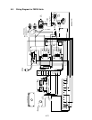
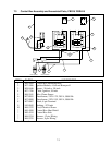
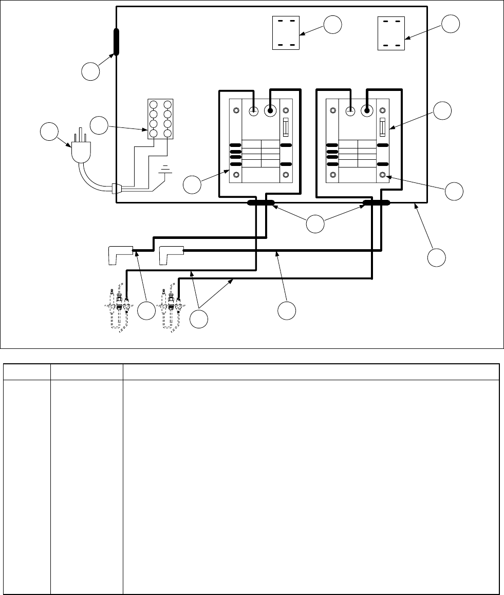
7.3 Control Box Assembly and Associated Parts, FBR18/ FBRA18
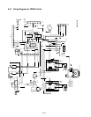
BLACK
WHITE
LEFT IGNITOR RIGHT IGNITOR
5
6
7
84
3
2
1
25V
(GND)
ALARM
VALVE
GND
(BURNER)
25V 25V
(BURNER)
GND
VALVE
ALARM
(GND)
25V
LOAD
LINE
12
120
120
24
LINE
LOAD
GREEN
5
44
2
RIGHTLEFT
7
6
8
10
9
9
2
3
1
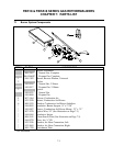
ITEM PART # COMPONENT
1 900-4509 Control Box Mounting Base
2 807-1006 Ignition Module, 4-Second Honeywell
3 809-0446 Spacer, .26-inch x .50-inch
4 807-1706 Cable, Ignition, 36-inch
5 806-5541 Wire, Flame Sensor
6 807-0855 Transformer, 120V-12V, 20VA, 50/60 Hz
7 807-0800 Transformer, 120V-24V, 50VA, 50/60 Hz
8 807-0067 Block, 8-pin Terminal
9 810-0045 Bushing, .875-inch
10 806-5332 Cord, Electrical Power
* 900-4508 Control Box Heat Shield
* 900-4510 Control Box Side
* 806-9334 Harness, 12-pin Wiring
* 806-9335 Harness, 9-pin Wiring
* Not illustrated.