


6-18
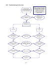
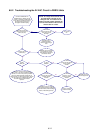
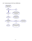
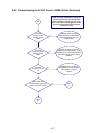
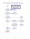
6.8.3 Troubleshooting the 24 VAC Circuit in FBRA18 Units (Continued)
NOTE: All voltage measurements involving the
gas valve leg of the 24V circuit must be made
within 4 seconds of unit calling for heat. If unit
does not fire within 4 seconds, ignition
modules will lock out and controller must be
turned off then back on to reset.
B
Is 24VAC
present across the gas
valve main coil (PV)
terminal?
Gas valve leg
of 24V circuit is
OK.
Is
24VAC present on
VALVE terminal of LEFT
ignition module?
Probable cause is
failed wiring between
module and gas valve.
Is 24VAC present
on 25V terminal of LEFT
ignition module?
If fuse is not
blown, module
has failed.
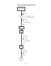
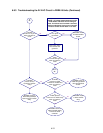
Is 24VAC
present on J2
pin 4?
Is 24VAC present
on 25V terminal of RIGHT
ignition module?
Is
24VAC present on
VALVE terminal of RIGHT
ignition module?
Probable cause
is failed wiring
harness.
Probable causes are failed
wiring between blower centrifugal
switch and module, failed
centrifugal switch, or failed
wiring harness.
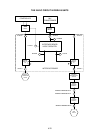
Is 24VAC
present on J2
pin 3?
Probable cause
is failed CYCLE
relay.
Probable cause is
failed wiring between
terminal block and J2
pin 3.
Yes
No
Yes
No
Yes
No
Yes
No
Yes
No
No
Yes
Yes
No