


6-14
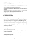
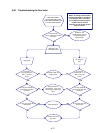
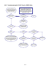
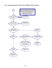
6.8.2 Troubleshooting the 24 VAC Circuit in FBR18 Units
NOTE: All voltage measurements must
be made within 4 seconds of unit
calling for heat. If unit does not fire
within 4 seconds, ignition modules will
lock out and controller must be turned
off then back on to reset.
UNIT IS CONNECTED TO
POWER SUPPLY, DRAIN VALVE
IS FULLY CLOSED, CONTROLLER
IS ON AND IS CALLING FOR HEAT
(decimal appears between first
two digits in controller display).
Is 24VAC present on
interface board J3 pin 9
(LED 5 (GV) lit)?
Is 24VAC
present across the gas
valve main coil (PV
terminal)?
24V circuit is
OK.
Probable cause is
failed wire between
interface board and gas
valve.
Is LED 3 (24V) lit
continuously?
Is LED 4
(PWR) lit?
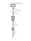
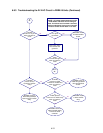
Is LED 2
(PWR) lit?
Is 24VAC
present on 25V terminal
of LEFT ignition
module?
Is 24VAC
present on VALVE
terminal of ignition
module?
Probable cause is
failed wiring harness.
If fuse is not blown,
module has failed.
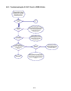
Is 24VAC
present on 25V terminal
of RIGHT ignition
module?
Probable causes are failed
wiring between blower centrifugal
switch and module, failed centrifugal
switch, or failed wiring harness.
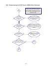
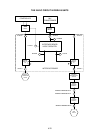
Check for 12VDC across interface
board J2 pins 4 & 5 when controller is calling
for heat. If 12VDC is not present, probable
causes are failed controller or failed relay on
interface board. On later design boards, relay K3
may be replaced. On earlier design boards,
the entire interface board must be
replaced..
Probable causes are failed
24V transformer or failed
wiring between transformer
and interface board.
Yes
No
Yes
No
Yes
No
Yes
No
Yes
No
Yes
No
Yes
No
Yes
No