


Part # 4525958 (05/15/09)Page 8
INSTALLATION continued
Gas Supply
A. The type of gas for which the unit is equipped is stamped
on the rating plate. Connect a unit stamped “NAT” only
to natural gas; connect those stamped “PRO” only to
propane gas.
B. If it is a new installation, have gas authorities check meter
size and piping to assure that the unit is supplied with
sucient amount of gas pressure required to operate the
unit.
C. If it is additional equipment or replacement, have a
qualied gas technician check the gas pressure to make
certain that existing gas facilities (meter, piping, etc.) will
deliver the BTU’S of gas required at the unit with no more
than 1/2” water column pressure drop. When checking
pressure, be certain that other equipment on the same
gas line is on at full rate.
NOTE: When checking pressure, be sure that all other
equipment on the same gas line is on. If the broiler has
been supplied with a regulator it has been preset to
match specications on the unit’s rating plate. All units
require regulators and should be adjusted accordingly to
manufacturer specications.
D. The appliance and its individual shut o (supplied by
others) must be disconnected from the gas supply piping
system during any pressure testing of that system at
pressures in excess of 1/2 PSI (3.45 KPa).
E. Gas supply connection is made in back lower left hand
corner of unit. A readily accessible approved type of hand
valve should be installed on each supply line. Test for
leaks – Do Not Use An Open Flame.
F. A pressure tap plug is supplied with the units and it
is installed on the manifold. The valve panel must be
removed to use the pressure tap. The gas pressure must
be checked when the unit is installed, to insure that the
unit gas pressure is the same as specied on the rating
plate. If necessary, pressure adjustments must be made at
the pressure regulator.
G. If it is a completely new installation, have gas lines,
meter size piping and piping installed and checked by a
qualied gas technician.
H. Make certain that the new piping, joints, and connections
have been made in a clean manner and have been
purged, so that the piping compound, chips, etc., will not
clog pilots, valves, and/or controls. Use pipe joint sealant
that is resistant to liqueed petroleum gas.
WARNING: Check gas connections for leaks. Use a soap
solution or similar means. Do Not Use An Open Flame!
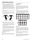
Gas Connections
All broilers have a rear gas 3/4” NPT or 3/4”-14NPT
connections. CE models have 3/4”-14 BSPT thread adapter.
NOTE: Adequate clearance must be provided for servicing
and proper operation.
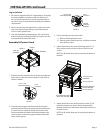
Counter Line Installations
Location
Unpack units carefully and provide the necessary space
on counter or back bar. All units must be installed in non-
combustible locations.
A. Location of the unit should be in an area where
make-up air is available to support proper combustion.
Make-up air should be supplied in such a manner as to
pass through the front of the unit. Do not obstruct front-
air ow.
B. In accordance with standard gas appliance operation,
the unit should be located under a ventilation hood of
applicable size and capacity. See ventilation instructions.
Sanitary Counter Top Seal
When the broiler is installed on a counter top, the National
Sanitation Foundation, (NSF), recommends that it be
sealed in accordance with NSF standards per the following
instructions:
1. Unit should be located on a non-combustible, level
counter top surface.
2. Thoroughly clean the bottom perimeter of the broiler and
the counter top around the bottom of the broiler.
3. Apply a generous bead of silicone sealant around the
entire outside perimeter of the broiler bottom.
4. The broiler can be secured to the counter top by inserting
the 3/8-inch diameter crating bolts through the counter
from the bottom, (via predrilled 1/2” diameter holes), and
threading them into the nut inserts in the bottom of the
unit.
5. Smooth the silicone sealant with a nger or tool to
provide a cover seal.