7
Installation Instructions.
Feed Water Adapter and Supply Valve
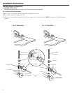
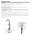
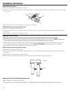
4. Assemble adapter (C) and coupling (D) as shown in Fig. 1, per your configuration. Be sure the gaskets (G) are in place before final
assembly. Start installation by hand, then finish tightening with adjustable wrench. Be careful not to overtighten or cross thread as
damage to threads may occur.
Note Adapter (C) orientation:
1/2-inch Installation—Rounded end of adapter (C) connects to coupling (D), then to existing faucet tubing (B).
3/8-inch Installation—Rounded end of adapter (C) connects to supply valve (A).
5. Hand tighten assembled adapter (C) onto supply valve (A) for the proper size installation. Be sure the gaskets (G), as shown
in Fig. 1, are in place before final assembly. Finish tightening with adjustable wrench. Be careful not to overtighten or cross
thread as damage to threads may occur.
NOTE: If inlet valve needs to be removed to complete this step, refer to D. Removal and Reinstallation of Inlet Valve on page 8.
6. Reconnect faucet tubing line (B) to top of adapter (C).
7. Remove nut and ferrule from end of inlet valve. Using the 4 feet of tubing provided, place the nut (I) and ferrule (H) onto
the tubing and install onto inlet valve (F) as shown in Fig. 2. Tighten with adjustable wrench.
NOTE: Inspect the ends of the tubing to be sure there are no imperfections and end of tubing is cut square. It may be necessary to cut the tubing again.
B. OPTIONAL HOME INSTALLATION—SADDLE VALVE
(Where codes permit): Saddle valve must be able to connect with 1/4-inch tubing supplied with system.
Not supplied with product; check your local hardware or home service store for product.
For 1/2″ OD or larger metal tubing only.
NOTE: Codes in the state of Massachusetts require installation by a licensed plumber and do not permit the use of the saddle valve.
For installation, use plumbing code 248-CMR of the Commonwealth of Massachusetts.
1. Turn off the cold water supply and install saddle valve as required by product selection. (Be sure to follow manufacturers’
installation instructions.)
DANGER: If hole is required to be drilled in pipe, to protect yourself from serious injury or fatal shock, use a battery
powered hand drill only to make the hole. DO NOT USE AN ELECTRIC DRILL.
Open only after complete system has been installed.
C. OPTIONAL INSTALLATION
(For installation with rigid pipe between supply valve and sink faucet)
Option 1
1. Remove pipe from supply valve and sink faucet.
2.
Obtain flexible pipe sized to your plumbing.
3. Install flexible pipe to sink.
4. Go back to A. Preferred Installation section step 4.
Option 2
1. Obtain compression fittings to fit rigid pipe.
2.
Obtain any other fittings required to connect compression fittings to adapter.
NOTE: Adapter has 1/2-inch and 3/8-inch internal and external threads.
3. Remove pipe from supply valve.
4. Cut pipe to fit length of assembled fittings and adapter.
5. Install compression fitting to pipe.
6. Go back to A. Preferred Installation section step 4.
NOTE: Above described materials are not included with the product.


