


32
INSTALLATION INSTRUCTIONS
(continued)
CONNECT THE RANGE TO GAS
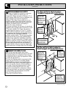
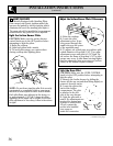
Shut off the main gas supply valve before
disconnecting the old range and leave it off until
new hook-up has been completed. Don’t forget
to relight the pilot on other gas appliances when
you turn the gas back on.
Because hard piping restricts movement of the
range, the use of an A.G.A.-certified flexible
metal appliance connector is recommended
unless local codes require a hard-piped connection.
Never use an old connector when installing a
new range. If the hard piping method is used,
you must carefully align the pipe; the range
cannot be moved after the connection is made.
To prevent gas leaks, use pipe joint compound
or wrap Teflon* pipe thread tape around all
male (external) pipe threads.
*Teflon: Registered trademark of DuPont
2
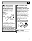
PROVIDE ADEQUATE GAS SUPPLY
Your range is designed to operate at a pressure
of 4″ of water column on natural gas or, if
designed for LP gas (propane or butane), 10″ of
water column. Make sure you are supplying your
range with the type of gas for which it is
designed. This range is convertible for use on
natural or propane gas. If you decide to use this
range on LP gas, conversion must be made by a
qualified LP installer before attempting to
operate the range on that gas.
For proper operation, the pressure of natural gas
supplied to the regulator must be between 4″ and
13″ of water column. For LP gas, the pressure
supplied must be between 10″ and 13″ of water
column. When checking for proper operation of
the regulator, the inlet pressure must be at least
1″ greater than the operating (manifold)
pressure as given above. The pressure regulator
located at the inlet of the range manifold must
remain in the supply line regardless of whether
natural or LP gas is being used. A flexible metal
appliance connector used to connect the range to
the gas supply line should have an I.D. of 1/2″
and be 5 feet in length for ease of installation. In
Canada, flexible connectors must be single wall
metal connectors no longer than 6 feet in length.
1
(continued next page)
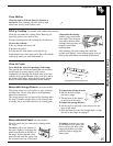
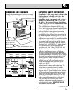
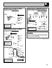
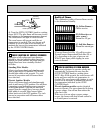
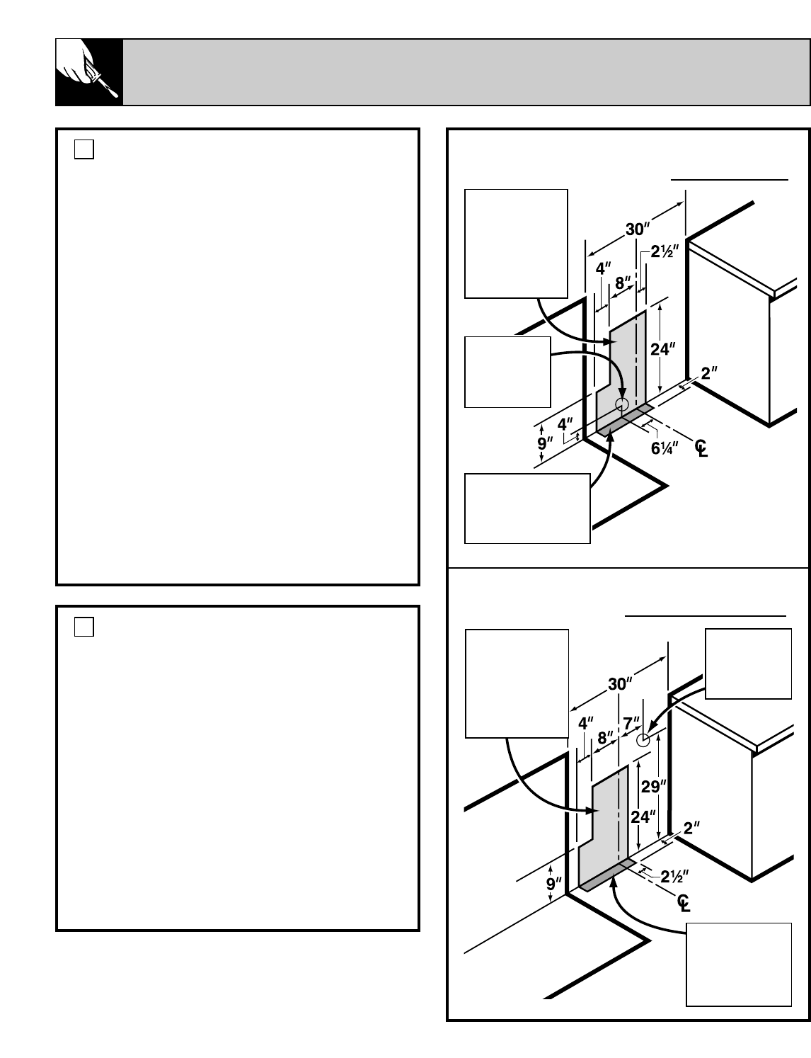
Gas Pipe and Electric Outlet Locations
for Models Equipped with Sealed Burners
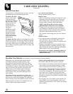
Gas Pipe and Electric Outlet Locations for
Models Equipped with Standard Twin Burners
This area allows
for flush range
installation with
through-the-wall
connection of pipe
stub/shut-off valve
and rear wall
120V outlet.
Shortest
connection
from hard pipe
stub location to
range hookup.
This area allows for
flush range installation
with through-the-floor
connection of pipe
stub/shut-off valve.
This area allows
for flush range
installation with
through-the-wall
connection of pipe
stub/shut-off valve
and rear wall
120V outlet.
Shortest
connection
from hard pipe
stub location to
range hookup.
This area allows
for flush range
installation with
through-the-floor
connection of pipe
stub/shut-off valve.