


16
Canopy Hood
®
HOOD SECTION VIEW
DEFLECTOR TO BE PLACED CENTERED
UNDER THE SUPPLY DUCT COLLAR
SU
PPL
Y
FIRE DAMPER
INTERNAL
SU
PPL
Y
C
HAMBE
R
H
OO
D
IN
SU
LATE
D
SU
PPLY PLEN
UM
EXHA
UST
C
APT
U
RE
SU
PPLY L
OC
ATI
O
N DETAIL F
OR
A
IR
CU
RTAIN AND
CO
MBINATI
ON
Hanger Bracket
Exhaust Plenum
Duct Cut Out Area
Duct Cut Out Area
Supply Plenum
Hood Length
Hood Width
Front of Hood
Exhaust Plenum
8.00 8.00
8.00
3.00
3.00
16.00
14.00
8.00
1.00
12.00
A
C
O
N
T
INU
O
U
S
L
I
Q
UID
T
I
G
H
T
W
E
L
D
T
O
H
OO
D.
E
X
H
A
U
S
T
DUC
T
C
O
NN
E
C
T
I
O
N I
S
T
O
B
E
C
O
NN
E
C
T
I
O
N
E
X
H
A
U
S
T
DUC
T
F
R
O
N
T
O
F
H
OO
D
H
A
N
G
E
R
BR
A
C
K
E
T
E
X
H
A
U
S
T
P
L
E
NUM
E
X
H
A
U
S
T
P
L
E
NUM
S
UPP
L
Y
P
L
E
NUM
DUC
T
CU
T
O
U
T
A
R
E
A
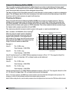
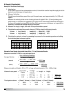
LABELED SUB-ASSEMBLY FOR EXHAUST HOOD WITHOUT EXHAUST DAMPER PART NO. DC.
2. U.L. LISTED HOOD ASSEMBLY TO BE USED ONLY WITH GREENHECK FAN CORP.
CENTER OF HOOD LENGTH TO CENTER OF DUCT CONNECTION.
NOTES: 1. EXHAUST DUCT CONNECTION TO BE LOCATED WITH IN 48" FROM
1
"
T
O
2
"
T
A
C
K
S
O
R
S
H
EE
T
M
E
T
A
L
S
C
R
E
W
S
A
T
3
"
T
O
6
"
S
P
A
CIN
G
T
O
H
OO
D.
S
UPP
L
Y
DUC
T
C
O
NN
E
C
T
I
O
N
T
O
B
E
T
A
C
K
W
E
L
D
E
D WI
T
H
C
O
NN
E
C
T
I
O
N
S
UPP
L
Y
DUC
T
DUC
T
CU
T
O
U
T
A
R
E
A
Hanger Bracket
Exhaust Plenum
Duct Cut Out Area
Duct Cut Out Area
Supply Plenum
Hood Length
Hood Width
Front of Hood
Exhaust Plenum
8.00 8.00
8.00
3.00
3.00
16.00
14.00
8.00
1.00
12.00
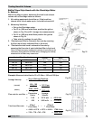
Back View of the Hood
Fig 25
Fig. 26 Fig. 27
Fig. 28
Note: UL listed hood
assembly to be used
only with Greenheck
Fan Corp. labeled
subassembly for
exhaust hood without
exhaust damper part
Number DC.
Hood Top
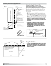
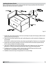
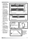
1. The exhaust duct
connection needs to
be located within 48 in.
(121.92 cm) from the
center of the hood
length to the center of
the duct connection.
(see Fig. 24, back view
Fig. 25)
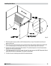
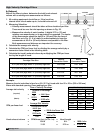
2. The exhaust duct
connection is to be
a continuous liquid-
tight weld. Weld with
a non-ferrous filler
wire, such as silicon
bronze or stainless
steel filler wire. Protect
all stainless steel areas
from weld splatter.
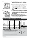
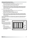
3. The supply duct
connection is tack-
welded at 1 to 2 in.
(2.54 to 5.08 cm)
intervals, or sheet metal
screws at 3 to 6 in.
(7.62 cm to 15.24 cm)
spacing to the hood.
(Fig. 26)
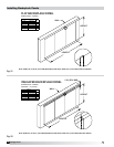
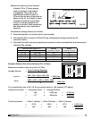
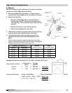
4. The deflector is
centered under the
supply duct collar.
(Fig. 28)
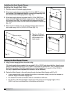
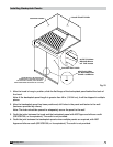
5. For hoods that are
insulated, the edges of
the insulation need to
be taped after the hole
is cut, (the insulation
tape is to be provided
by others).
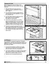
6. On combination hoods,
make sure the fire
damper is located over
the internal supply
chamber. (Fig. 29)
Top View of the Hood
Fig. 24
Installing Duct Collars