


28
Canopy Hood
®
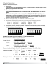
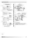
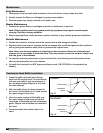
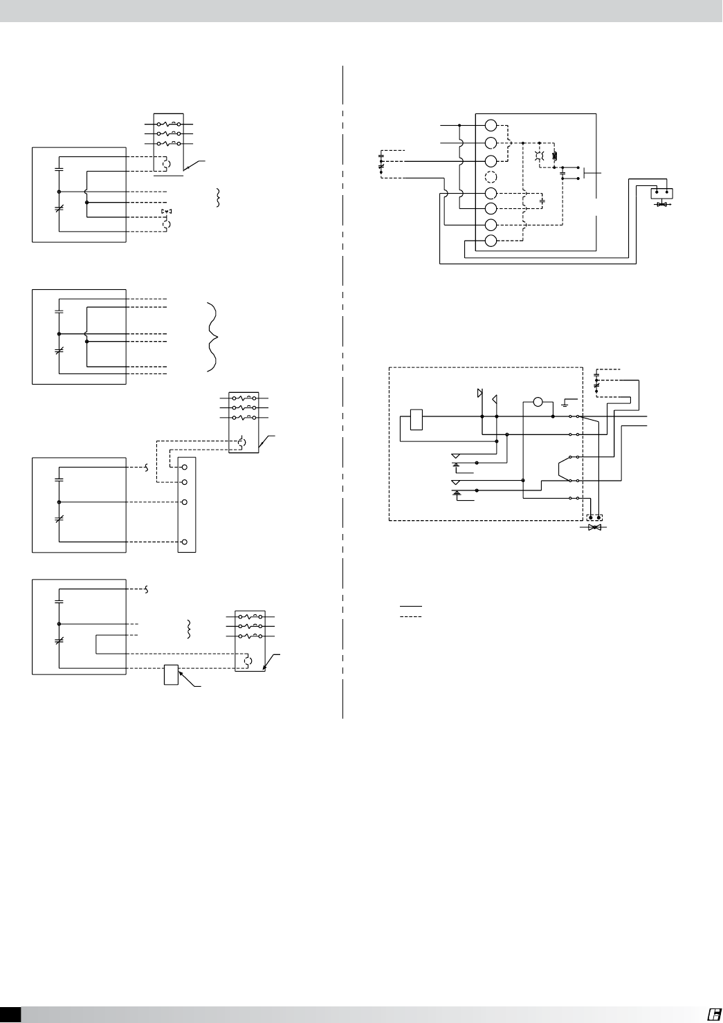
Field Wiring for the Ansul Snap-Action Switch
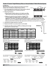
Option A
Relay Part No. 14702
* K1a and K1b are N.O. when K1 is de-energized
Manual Reset Relay
Part No. 14702
K1*
N.O.
K1a
K1b
N.O.
Push Button
Switch
Gas Valve
See Note 3
1
2
3
5
6
7
8
L1
110V/60HZ
Black
Red
Brown
L2
Snap-Action Switch
Part No. 423878
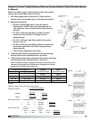
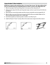
Option B
Relay Part No. 426151
Ansul Snap-Action Switch
(Switch contacts shown with Ansul
Automan in the cocked position)
Snap-Action Switch
Part No. 423878
Black
Red
Brown
L2 Neutral
L1 Hot
110 VAC/60HZ
5
4
3
2
1
GND
Screw
Power
Indicator
Reset
AB
Relay Coil
Manual Reset Relay
(Part No. 426151)
Electrical Rating
1/3 HP, 10 AMP, 120 VAC
1/2 HP, 10 AMP, 240 VAC
13 AMP, 28 VDC
Gas Valve
See Note 3
6
9
3
4
7
1
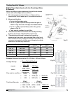
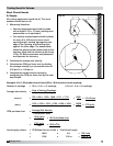
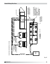
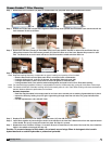
2 Snap-Action Switches provided by Greenheck
may be wired as shown.
Four typical examples shown
Power to cooking
equipment
Shunt Trip Breaker
120 VAC
N
Input
NO
NC
Electric gas valve - If reset relay is
used, see option A or B at right.
Mechanical gas shut off valve does not
require electrical connection.
NO
NC
NO
Input
NC
Voltage Free
Contacts for
Building Alarm(s)
Power to
Fan(s)
Fan
Starter
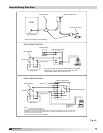
Terminal strip in
Waterwash Control Panel
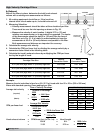
NO
NC
3
4
5
6
NO
NC
120 VAC
N
Input
Power to
fan(s)
Fan Starter
Manual Switch
If prohibited by local codes, do not shut down
exhaust fans with this method of wiring.
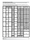
Note:
1. Denotes field installation.
2. Denotes factory installation.
3. Gas Valves: “UL Listed electrically-operated safety valve for natural or LP gas
as needed of appropriate pressure and temperature rating, 110V/60HZ”
or Ansul gas valves.
4. Do not use black wire on snap-action switch in normal installation. Black
wire may only be used for extraneous alarm, light circuits, etc.
Equipment
Alarms
Waterwash
Fans
Ansul Wiring Plan View
Fig. 47