


14
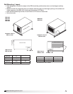
Model ERV Energy Recovery Unit
• Aftertesting,settheTimerScaleasfollows:
T1 = 10 minutes, T2 = 1 hour
• SettheTimerSettingsasfollows:
T1 = 0.5, T2 = 0.5
The timer is now set for 5 minutes off and 30
minutes on. Remember to remove the jumper.
Electric preheat frost control includes an electric
heater (at outdoor air intake) and an airflow pressure
switch (located at the preheater) in addition to the
thermostat and pressure sensor on wheel. (Refer
to Electric Heater Application/Operation for electric
preheater location). When electric preheat frost
control is initiated, the electric preheater will turn
on and warm the air entering the energy wheel to
avoid frosting. Use the following test procedure for
troubleshooting.
Testing:
• Turnthethermostatashighasitwillgoand
jumper the wheel pressure sensor. The heater
should turn on.
• Ifitdoesn’t,eitherputtheoutdoorairsidedoors
on or temporarily jumper the airflow pressure
switch in the preheater control center to avoid
nuisance tripping of the pressure switch. Also
check the airflow switch pressure tap located
at the supply discharge blower to ensure the
tubing is connected and the tap is not blocked.
Remember to remove the jumpers.
Modulating wheel frost control includes a variable
frequency drive in addition to the thermostat and
pressure sensor. When modulating wheel frost control
is initiated, the variable frequency drive will reduce
the speed of the wheel. Reducing the speed of the
energy wheel reduces its effectiveness, which keeps
the exhaust air condition from reaching saturation,
thus, eliminating condensation and frosting. If the
outdoor air temperature is greater than the frost
threshold temperature OR the pressure differential
is less than the set point, the wheel will run at full
speed. If the outdoor air temperature is less than
the frost threshold temperature AND the pressure
differential is greater than the set point, the wheel will
run at reduced speed until the pressure differential
falls below the set point. The temperature and
pressure differential set points are set at the factory,
but are field-adjustable (refer to VFD section for more
information). The variable frequency drive will be fully
programmed at the factory.
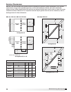
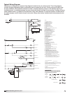
Frost Control Application/Operation
Extremely cold outdoor air temperatures can cause
moisture condensation and frosting on the energy
recovery wheel. Frost control is an optional feature
that will prevent/control wheel frosting. Three options
are available:
1. Timed Exhaust frost control
2. Electric preheat frost control
3. Modulating wheel frost control
All of these options are provided with a thermostat
(with probe) mounted in the outdoor air intake
compartment and a pressure sensor to monitor
pressure drop across the wheel.
The typical temperature setting corresponds to the
indoor air relative humidity as shown in the Frost
Threshold Temperatures table and represents when
frost can occur. An increase in pressure drop would
indicate that frost is occurring. Both the pressure
sensor and the outdoor air temperature sensor
must trigger in order to initiate frost control. The
two sensors together insure that frost control is
only initiated during a real frost condition. Field
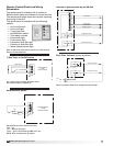
wiring of a light (or other alarm) between 6 & C in
the control center will notify personnel when unit is
in frost control mode (refer to Remote Panel Wiring
schematics section for wiring details). The following
explains the three options in more detail.
Timed exhaust frost control includes a timer in
addition to the thermostat and wheel pressure sensor.
When timed exhaust frost control is initiated, the
timer will turn the supply blower on and off to allow
the warm exhaust air to defrost the energy recovery
wheel. Default factory settings are 5 minutes off and
30 minutes on. Use the following test procedure for
troubleshooting.
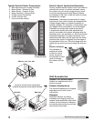
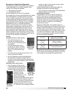
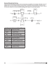
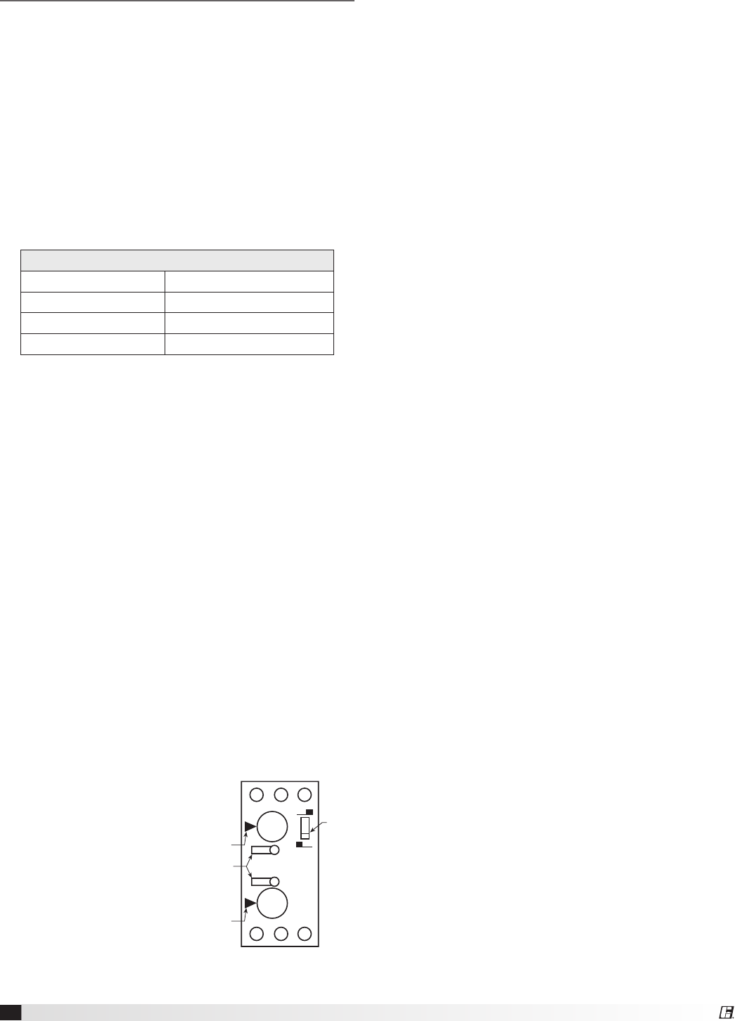
Testing (refer to Timer Faceplate drawing below)
• Jumperthewheel
pressure switch in the
unit control center. Set
the Timer Scale for T1
and T2 to 1 minute. Set
the Timer Settings for
T1 and T2 to 1.0. Set the
dip switch to the down
position. (normal position)
• Turnthetemperature
sensor up as high as
possible. The supply blower should cycle on for
one minute, then turn off for one minute.
Frost Threshold Temperatures
Indoor RH @ 70°F Frost Threshold Temp
20% -10º F
30% -5º F
40% 0º F
A1 B1 15
16 18 A2
0.20
0.41.0
0.60.8
0.20
0.41.0
0.60.8
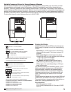
T1
T2
T21 MIN
T11 MIN
Timer
Scale
Dip
Switch
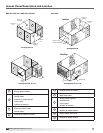
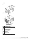
Optional Accessories