


3
Model ERV Energy Recovery Unit
Table of Contents
Basic Operation . . . . . . . . . . . . . . 3
Installation
Supplemental Installation, Operation and
Maintenance Manuals . . . . . . . . . . . 3
Installation Concerns. . . . . . . . . . . . 3
Lifting . . . . . . . . . . . . . . . . . . 4
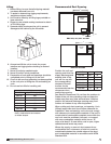
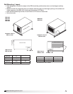
Roof Curb and Rail Mounting
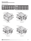
Recommended Roof Opening . . . . . . . . 4
Roof Curb Mounting . . . . . . . . . . . . 5
Curb Dimensions and Weights . . . . . . . . 5
Ductwork Connections . . . . . . . . . . . 5
Rail Mounting / Layout . . . . . . . . . . . 6
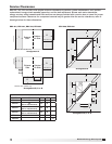
Service Clearances . . . . . . . . . . . . 7
Electrical Information
General Electrical Information . . . . . . . . 8
Control Center Components. . . . . . . . . 9
Electric Heater Application/Operation . . . . . 9
Unit Accessories. . . . . . . . . . . . . . 9
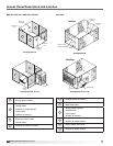
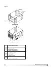
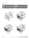
Access Panel Description and Location . .10-11
Dimensional Data . . . . . . . . . . . . 12-13
Optional Accessories
Frost Control Application/Operation . . . . . 14
Economizer Application/Operation . . . . . . 15
Variable Frequency Drives and Wiring . . . .16-17
Typical Wiring Diagram . . . . . . . . . . . 18
Sensors and Lights . . . . . . . . . . . . 19
Remote Control Panel and Wiring . . . . . . 20
Sensors Mounted by Factory . . . . . . . . 21
Sequence of Operation
Start-Up
Unit . . . . . . . . . . . . . . . . . . . 22
Optional Accessories . . . . . . . . . . . 23
Fan . . . . . . . . . . . . . . . . . . . 24
Energy Recovery Wheel . . . . . . . . . . 25
Routine Maintenance Checklist
General . . . . . . . . . . . . . . . . . 26
Fan Belts. . . . . . . . . . . . . . . . . 26
Fan Motors . . . . . . . . . . . . . . . . 26
Fan Wheel and Fasteners . . . . . . . . . . 27
Fan Bearings . . . . . . . . . . . . . . . 27
Filters . . . . . . . . . . . . . . . . . . 27
Door Seal Maintenance. . . . . . . . . . . 27
Energy Recovery Wheel Maintenance
Accessing Energy Recovery Wheel . . . .27-28
Removing Wheel Segments . . . . . . . . 28
Cleaning Wheel Segments . . . . . . . . 29
Wheel Belt . . . . . . . . . . . . . . . 29
Wheel Bearing . . . . . . . . . . . . . 29
Parts List . . . . . . . . . . . . . . . . . 30
Sequence of Operation . . . . . . . . . . . 31
Troubleshooting – Airflow. . . . . . . . . . 32
Troubleshooting – Unit . . . . . . . . . 33-34
Maintenance Log . . . . . . . . . . . . . 35
Warranty . . . . . . . . . . . . . Backcover
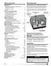
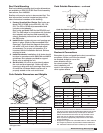
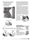
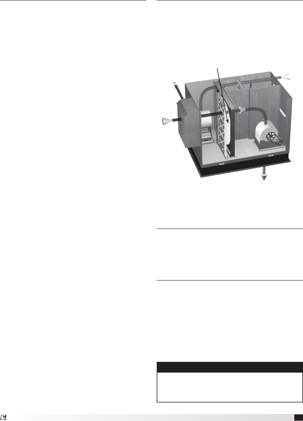
Basic Operation
The ERV brings in fresh, outdoor air and removes
stale, exhaust air. Prior to discharging the exhaust
air, the energy recovery wheel transfers energy from
the exhaust air to the outdoor air at an efficiency
of 70-80%. Simply put, this unit preconditions the
outdoor air to save money on heating and cooling
costs.
Outdoor
air
Exhaust air
discharged
outside
Exhaust air
from building
Preconditioned air
sent to space
Energy Recovery
Wheel
Installation
The system design and installation should follow
accepted industry practice, such as described in the
ASHRAE Handbook.
Adequate space should be left around the unit for
filter replacement and maintenance. Sufficient space
should be provided on the side of the unit for routine
service and component removal should that become
necessary.
See Service Clearances and Access Panel Description
sections for more details.
Supplemental Installation,
Operation and Maintenance
Manuals
Refer to the following Installation, Operation and
Maintenance Manuals for additional details:
Part #460988 — ERV-522 and ERV-582 Curbs
Part #462844 — ERV Exhaust Weatherhood
WARNING
All factory provided lifting lugs must be used when
lifting the unit. Failure to comply with this safety
precaution could result in property damage, serious
injury or death.