


8
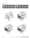
Model ERV Energy Recovery Unit
Electrical Information
The unit must be electrically grounded in accordance
with the current National Electrical Code, ANSI/NFPA
70. In Canada, use current CSA Standard C22.1,
Canadian Electrical Code, Part 1. In addition, the
installer should be aware of any local ordinances or
electrical company requirements that might apply.
System power wiring must be properly fused and
conform to the local and national electrical codes.
System power wiring is to the unit main disconnect
(door interlocking disconnect switch standard
on most units) or distribution block and must be
compatible with the ratings on the nameplate: supply
power voltage, phase, and amperage (Minimum
Circuit Amps - MCA, Maximum Overcurrent Protection
- MOP). All wiring beyond this point has been done
by the manufacturer and cannot be modified without
affecting the unit’s agency / safety certification.
If field installing an additional disconnect switch, it
is recommended that there is at least four feet of
service room between the switch and system access
panels. When providing or replacing fuses in a fusible
disconnect, use dual element time delay fuses and
size according to the rating plate.
If power supply is desired through bottom of unit, run
the wiring through the curb, cut a hole in the cabinet
bottom, and wire to the disconnect switch. Seal
penetration in cabinet bottom to prevent leakage.
The electric supply to the unit must meet stringent
requirements for the system to operate properly.
Voltage supply and voltage imbalance between
phases should be within the following tolerances.
If the power is not within these voltage tolerances,
contact the power company prior to operating the
system.
Voltage Supply: See voltage use range on the rating
plate. Measure and record each supply leg voltage at
all line disconnect switches. Readings must fall within
the allowable range on the rating plate.
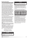
Voltage Imbalance: In a 3-phase system, excessive
voltage imbalance between phases will cause motors
to overheat and eventually fail. Maximum allowable
imbalance is 2%. To determine voltage imbalance,
use recorded voltage measurements in this formula.
Key: V1, V2, V3 = line voltages as measured
VA (average) = (V1 + V2 + V3) / 3
VD = Line voltage (V1, V2 or V3) that
deviates farthest from average (VA)
Formula: % Voltage Imbalance = [100 x (VA-VD)] / VA
WARNING
To prevent injury or death due to electrocution or
contact with moving parts, lock disconnect switch
open.
CAUTION
If any of the original wire as supplied with the
appliance must be replaced, it must be replaced
with wiring material having a temperature rating of
at least 105ºC.
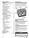
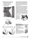
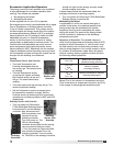
Most factory supplied electrical components are
prewired. To determine what electrical accessories
require additional field wiring, refer to the unit specific
wiring diagram located on the inside of the unit
control center access door. The low voltage control
circuit is 24 VAC and control wiring should not exceed
0.75 ohms.
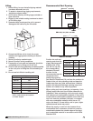
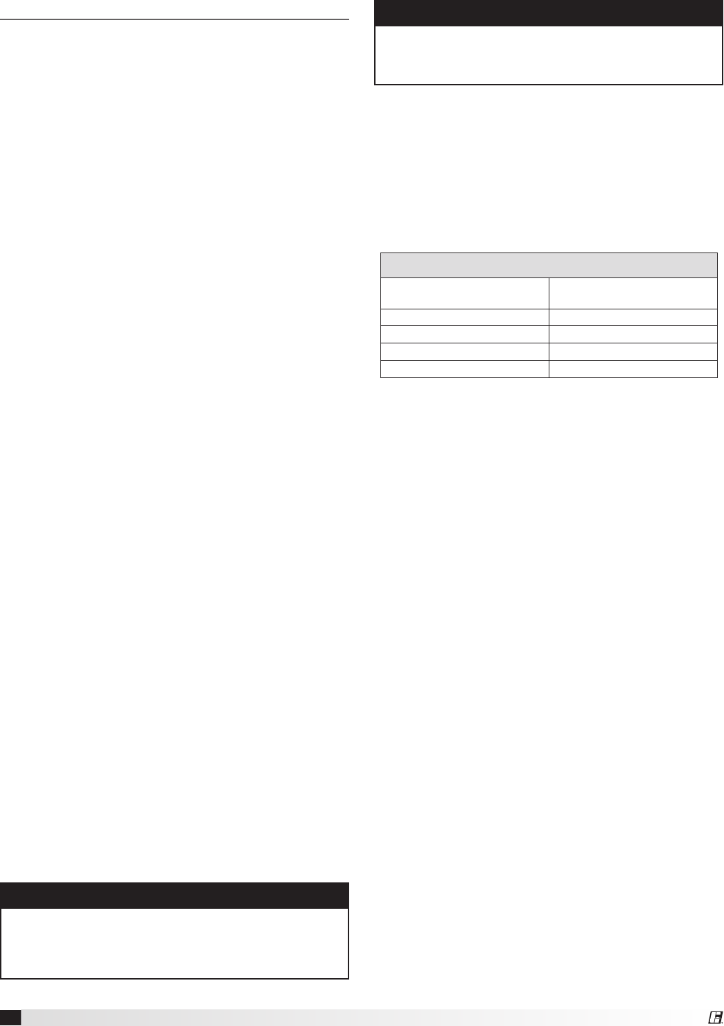
Refer to Field Control Wiring Length/Gauge table for
wire length maximums for a given wire gauge.
Control wires should not be run inside the same
conduit as that carrying the supply power. Make sure
that field supplied conduit does not interfere with
access panel operation.
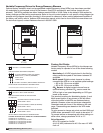
If wire resistance exceeds 0.75 ohms, an industrial-
style, plug-in relay should be added to the unit
control center and wired in place of the remote
switch (typically between terminal blocks R and G
on the terminal strip (refer to Typical Control Center
Components). The relay must be rated for at least
5 amps and have a 24 VAC coil. Failure to comply
with these guidelines may cause motor starters to
“chatter” or not pull in which can cause contactor
failures and/or motor failures.
Field Control Wiring Length/Gauge
Total
Wire Length
Minimum
Wire Gauge
125 ft. 18
200 ft. 16
300 ft. 14
450 ft. 12