


16
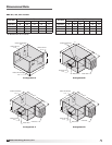
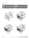
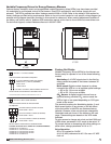
Model ERV Energy Recovery Unit
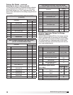
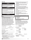
Factory Set Points
Variable Frequency Drives (VFDs) for the blowers are
factory setup to operate in one of the three following
modes:
Modulating: 0-10 VDC signal wired in the field by
others varies the speed of the blower between 30
and 60Hz
Multi-speed: Digital contact closures by others
command the VFD to run at multiple speed settings:
•SCtoS4-Driverunsat40Hz
•SCtoS5-Driverunsat30Hz
CO
2
Sensor: A digital contact closure from an
optional factory provided CO
2
sensor sends the
VFD to high or low speed depending on CO
2
ppm
levels at the sensor.
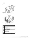
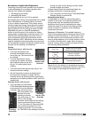
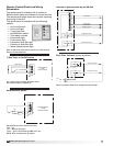
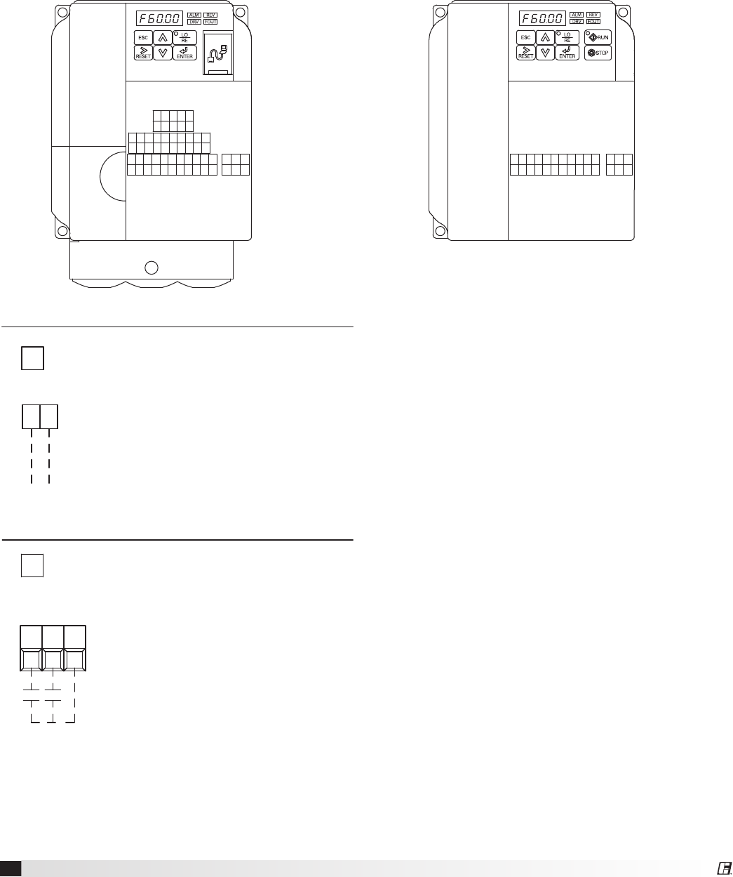
The terminal locations for Modulating (option 1) and
Multi-speed (option 2) are shown on the left. Most
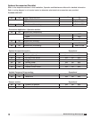
of the set points in the VFDs are Yaskawa factory
defaults. However, a few set points are changed at
Greenheck and are shown in the tables on the next
page. These settings are based on the VFD mode
selected.
To gain access to change set points on the V1000 and
J1000drives,parameterA1-01needstobesetat“2”.
To prevent access or tampering with drive settings on
either drive, change parameter A1-01 to “0”.
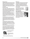
Drive Operation
SC to S1 contact for On/Off
A1 (0-10 VDC) referenced to AC. Can use +15 VDC
from +V
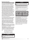
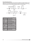
Variable Frequency Drives for Energy Recovery Blowers
Optional factory installed, wired, and programmed variable frequency drives (VFDs) may have been provided
for modulating or multi-speed control of the blowers. One VFD is provided for each blower (supply air and
exhaust).TheVFD’sprovidedareeitherYaskawamodelV1000orJ1000.Refertothetablesinthissectionfor
factory settings and field wiring requirements. Refer to the unit control center for unit specific wiring diagram (an
example wiring diagram has been provided in this manual for reference). When making adjustments outside of
the factory set points, refer to Yaskawa VFD instruction manual, which can be found online at www.drives.com.
For technical support, contact Yaskawa direct at 1-800-927-5292.
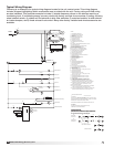
MAMB MCRPH1SCHCS7S6S5S4S3S2S1
MPACAMAC+VA2A1PCP2P1
IGS-S+R-R+
V1000
MAMBMCACAMAC+VA1SCS5S4S3S2S1
J1000
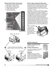
OPTION 1 - 0-10 VDC CONTROL
SEE VFD INSTALLATION MANUAL FOR MORE DETAIL
USER TO PROVIDE ISOLATION AS REQUIRED
FOR CONTINUOUS 60Hz OPERATION JUMPER TERMINALS A1 AND +V.
WIRED TO A1 (+) AND AC (COMMON)
0-10 VDC CONTROL SIGNAL (BY OTHERS)
10 VDC=60 Hz
0 VDC=30 Hz
A1 AC
FOR ONE 0-10 SIGNAL, WIRE TO DRIVES IN PARALLEL
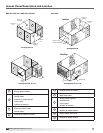
OPTION 2 - MULTI SPEED CONTROL
S5S4 SC
NEITHER S4 OR S5 CONTACT CLOSED
DRIVE SPEED = 60 Hz.
DRIVE SPEED = 40 Hz.
S4 TO SC CONTACT CLOSED (BY OTHERS)
S5 TO SC CONTACT CLOSED (BY OTHERS)
DRIVE SPEED = 30 Hz.
TO CHANGE THE FACTORY SET Hz CHANGE THE FOLLOWING PARAMETERS.
PARAMETER n01 CHANGE TO 1
PARAMETER n22 FOR NEW 40Hz SETTING
PARAMETER n21 FOR NEW 60Hz SETTING
PARAMETER n23 FOR NEW 30Hz SETTING
PARAMETER n01 CHANGE TO 0
USER TO PROVIDE CONTACTS AND ISOLATION
AS REQUIRED
SEE VFD INSTALLATION MANUAL FOR MORE DETAIL