


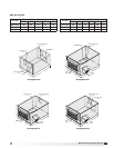
5
Model ERV Energy Recovery Unit
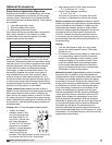
1 Fan
Wheel
Dia.
1 Fan
Wheel
Dia.
R
o
t
a
t
i
o
n
R
o
t
a
t
i
o
n
R
o
t
a
t
i
o
n
R
o
t
a
t
i
o
n
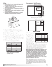
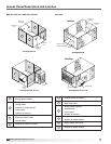
Length of Straight Duct
GOOD
POOR
GOODPOOR
GOOD
POOR
Turning
Vanes
Turning
Vanes
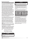
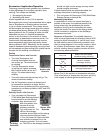
SYSTEM EFFECT FACTOR CURVES
FPM X 100
OUTLET VELOCITY
0 5 10 15 20 25 30 35 40 45
1.2
1.0
0.8
0.6
0.4
0.2
0.0
STATIC PRESSURE LOSS
CURVE 1
CURVE 2
CURVE 3
CURVE 4
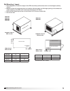
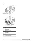
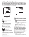
Roof Curb Mounting
Roof curb details including duct location dimensions,
are available on ERV-522 & 582 Roof Curb Assembly
Instructions, Part #460988.
Rooftop units require curbs to be mounted first. The
duct connections must be located so they will be
clear of structural members of the building.
1. Factory Supplied Roof Curbs: Roof curbs are
Model GPI or GPNS for the ERV-251, 361, 521,
581. The GPI or GPNS ships assembled and
includes a duct adapter.
Roof curbs are Model GKD for the ERV-522 and
582. The GKD ships in a knockdown kit (includes
duct adapter) and requires field assembly (by
others). Assembly instructions are included with
the GKD curbs.
2. Install Curb: Locate curb over roof opening and
fasten in place. (Refer to Recommended Roof
Openings). Check that the diagonal dimensions
are within ±1/8 inch of each other and adjust
as necessary. For proper unit operation, it is
important that the installation be level. Shim as
required to level.
3. Install Ductwork: Installation of all ducts should
be done in accordance with SMACNA and AMCA
guidelines. Duct adapter provided to support
ducts prior to setting the unit.
4. Set the Unit: Lift unit to a point directly above
the curb and duct openings. Guide unit while
lowering to align with duct openings. Roof curbs
fit inside the unit base. Make sure the unit is
properly seated on the curb and is level.
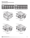
Unit Size L W Curb Weight (lbs.)
ERV-251 42.5 30.5 60
ERV-361 58.5 47.5 115
ERV-521 63.5 63.5 160
ERV-581 71.8 66 185
ERV-522 120.5 80.5 520
ERV-582 142.25 93 700
All dimensions are in inches. Weights are for 12-inch high
GPI type curbs.
W
L
ERV-251, 361, 521 and 581
W
L
ERV-522 and 582
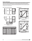
Curb Outside Dimensions and Weights
Roof Curb
Side of Unit
Base
1-inch Insulation
E
D
C
A
B
Unit Size A
B C D E
ERV-251 1.75 2.00 1.00 1.125 0.750
ERV-361 1.75 2.00 1.00 1.200 0.875
ERV-521 1.75 2.00 1.00 0.813 0.875
ERV-581 1.75 2.00 1.00 0.813 0.750
ERV-522 1.813 4.00 1.75 1.000 0.750
ERV-582 1.938 4.125 1.938 1.125 0.625
All dimensions are in inches.
Curb Cap Details for Factory Supplied Roof Curbs
Curb Outside Dimensions - continued
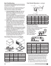
Recommended Discharge Duct Size and Length
Model Blower Size Duct Size Straight Duct Length
ERV-251 10 9 x 9 36
ERV-361 10 14 x 14 36
ERV-521 12 20 x 20 36
ERV-581 15 28 x 28 60
ERV-522S 15 28 x 28 60
ERV-522H 18 32 x 32 60
ERV-582 20 34 x 34 72
All dimensions shown in inches.
• Recommendedductsizesarebasedonvelocitiesacrossthe
cfm range of each model at approximately 800 feet per minute
(FPM) at minimum airflow and up to 1600 fpm at maximum
airflow. Recommended duct sizes are only intended to be a
guide and may not satisfy the requirements of the project.
Refer to plans for appropriate job specific duct size and/or
velocity limitations.
• Straightductlengthswerecalculatedbasedon100%effective
duct length requirements as prescribed in AMCA Publication
201. Calculated values have been rounded up to nearest foot.
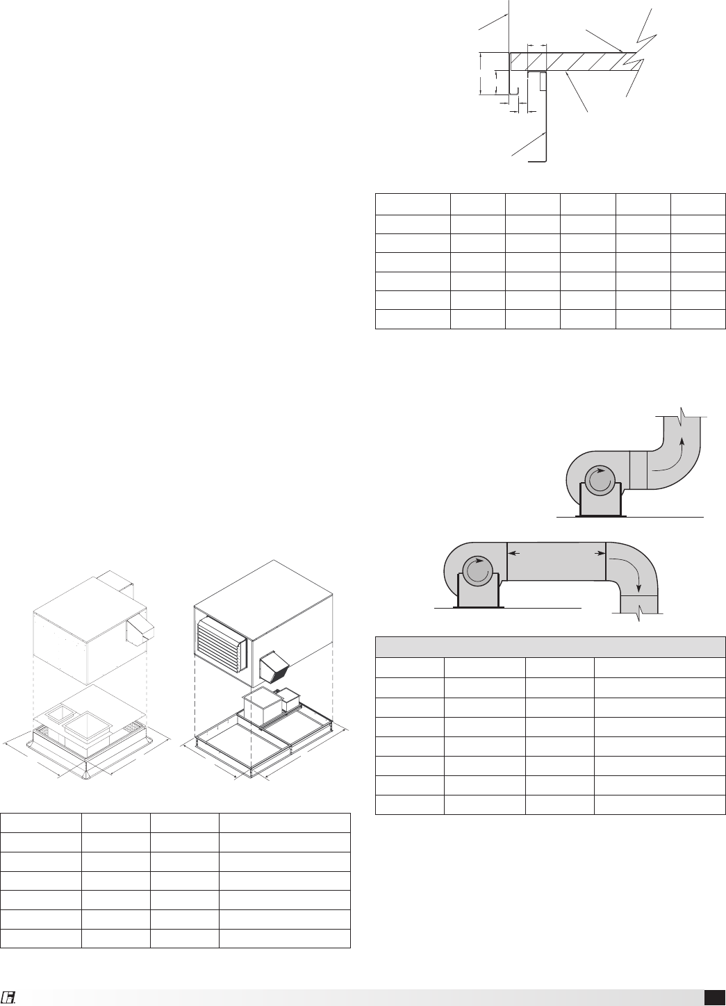
Ductwork Connections
Examples of poor and good fan-to-duct connections
are shown. Airflow out of the fan should
be directed straight or curve the
same direction as the
fan wheel rotates. Poor
duct installation will
result in low airflow and
other system effects.
1 Fan
Wheel
Dia.
1 Fan
Wheel
Dia.
R
o
t
a
t
i
o
n
R
o
t
a
t
i
o
n
R
o
t
a
t
i
o
n
R
o
t
a
t
i
o
n
Length of Straight Duct
GOOD
POOR
GOODPOOR
GOOD
POOR
Turning
Vanes
Turning
Vanes
SYSTEM EFFECT FACTOR CURVES
FPM X 100
OUTLET VELOCITY
0 5 10 15 20 25 30 35 40 45
1.2
1.0
0.8
0.6
0.4
0.2
0.0
STATIC PRESSURE LOSS
CURVE 1
CURVE 2
CURVE 3
CURVE 4