


Model OFE/OFG/OEA/OGA-341, 342
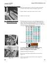
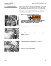
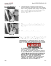
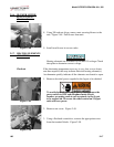
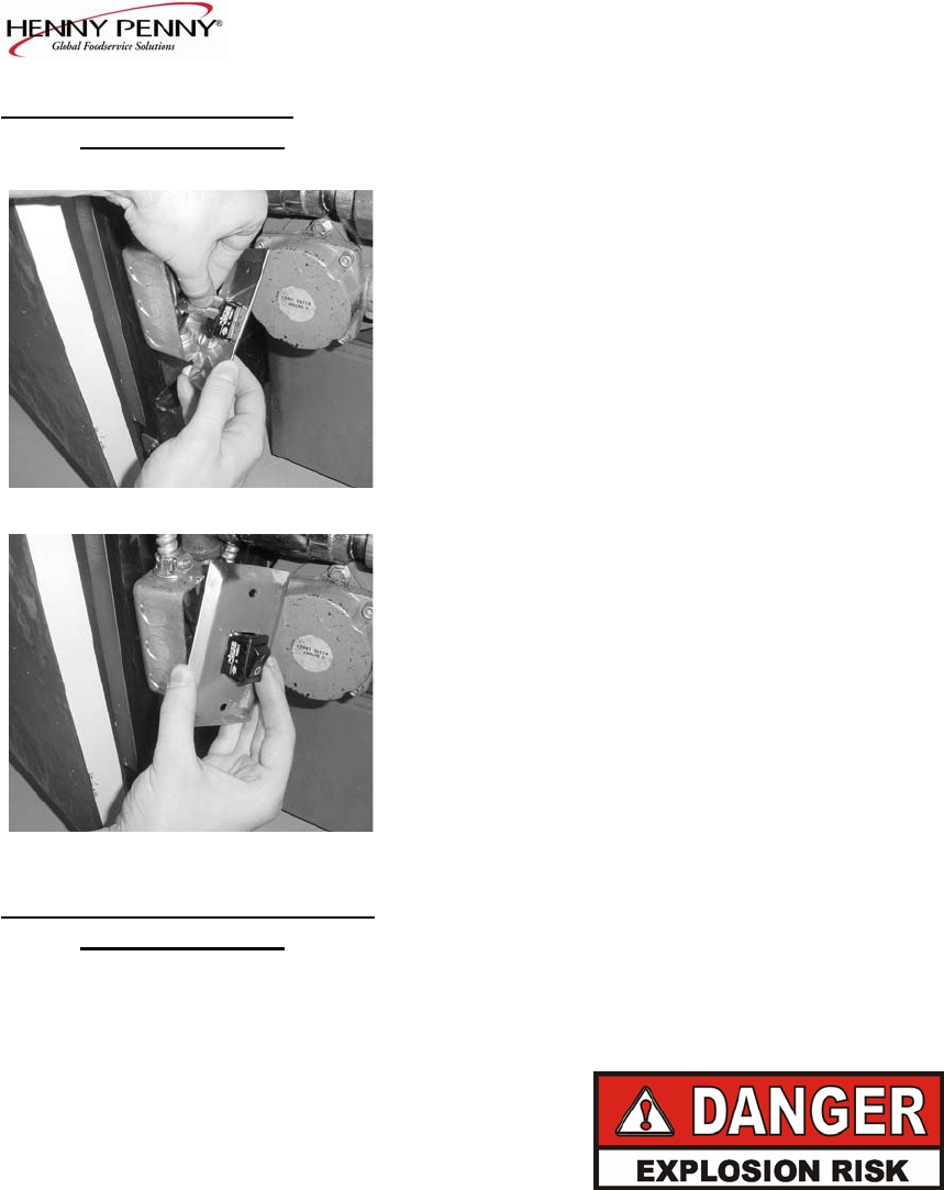
2-14. FILTER SWITCH 3. Label and remove the wires from the switch. With test
REPLACEMENT
instrument check across the terminals of the switch. With the
(Continued) switch in the on position, the circuit should be closed. With the
switch in the off position, the circuit should be open. If the
switch is defective, replace by continuing with this
procedure. Figure 2-35.
Figure 2-35
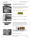
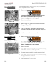
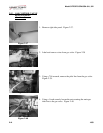
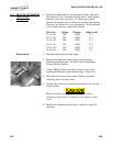
4. With wires removed from the switch, push in on tabs on the
switch and remove switch from front of switch box cover.
Figure 2-36.
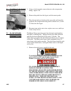
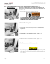
5. Push new switch into panel and reconnect wires.
Figure 2-36
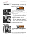
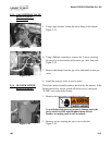
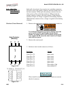
2-15. GAS CONTROL VALVE
The gas valve assembly controls the flow of gas to the pilot and the
REPLACEMENT
main burner. The valve has two 24-volt coils, which are regulated
by the P and M terminals on the valve. The C terminal is the
common terminal. For gas flow to the pilot, 24 VAC must be
present between the P and C terminals. For gas flow to the main
burner, 24 VAC must be present between the M and C terminals.
TO AVOID PERSONAL INJURY OR PROPERTY
DAMAGE, BEFORE STARTING THIS
PROCEDURE, MOVE THE MAIN POWER SWITCH
TO THE OFF POSITION. DISCONNECT THE MAIN
CIRCUIT BREAKERS AT THE CIRCUIT BREAKER
BOX OR UNPLUG SERVICE CORD FROM WALL
RECEPTACLE. TURN OFF THE MAIN GAS
SUPPLY TO THE FRYER AND DISCONNECT AND
CAP THE MAIN SUPPLY LINE TO FRYER, OR
POSSIBLE EXPLOSION COULD RESULT.
1003 2-13