


Model OFE/OFG/OEA/OGA-341, 342
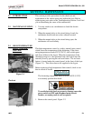
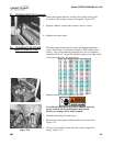
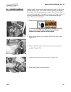
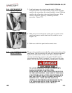
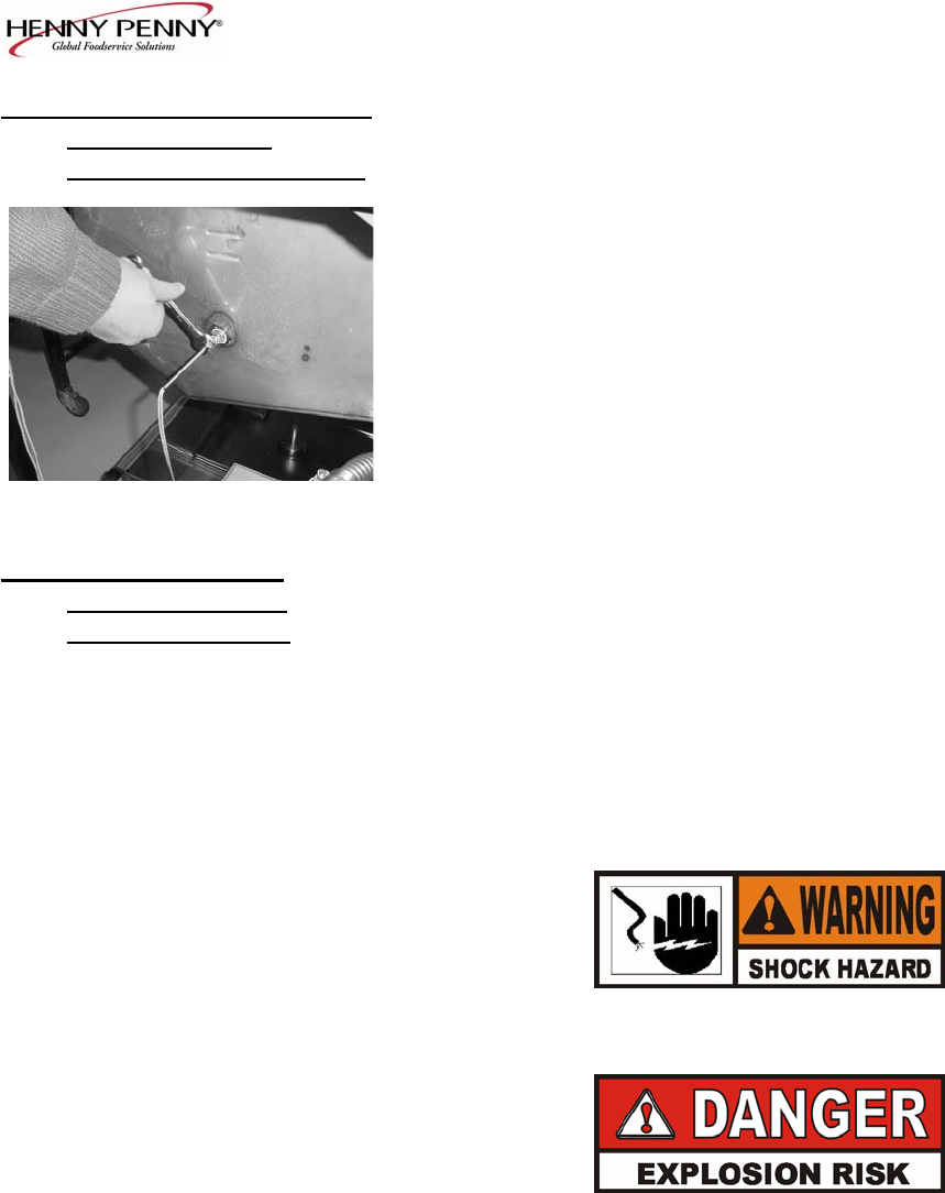
2-7. TEMPERATURE PROBE 4. Using a ½ inch wrench, remove the nut on the compression
REPLACEMENT
fitting. Figure 2-18.
(ELECTRIC) (Continued)
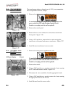
5. Remove the probe from the frypot, and disconnect probe.
6. Place the nut and new ferrule on the new probe and insert the
probe into the compression fitting until it extends one (1) inch
(2.54cm) into the frypot.
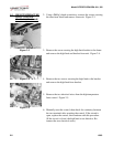
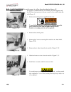
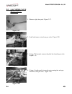
7. Reconnect new probe onto wires, replace rear cover, and fryer
Figure 2-18 is now ready for use.
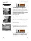
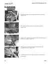
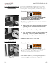
2-8. FLAME SENSOR/
The Henny Penny open fryer (gas) has electronic spark ignition
PILOT / IGNITOR
that lights a standing pilot. The gap between the spark electrode
ASSEMBLY (GAS)
and the pilot hood should be1/8 of an inch (3.18 mm). The
flame sensor recognizes the pilot flame and allows gas to continue
to the pilot. The flame sensor must send a minimum of two (2)
micro amps to the ignition module. The pilot flame should be split
in two by the flame sensor, causing the flame sensor to be bright
red in color.
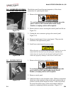
1. Remove electrical power supplied to the unit.
To avoid electrical shock or property damage, move the
power switch to OFF and disconnect main circuit
breaker, or unplug cord at wall receptacle.
TO AVOID PERSONAL INJURY OR PROPERTY
DAMAGE, BEFORE STARTING THIS
PROCEDURE, MOVE THE MAIN POWER SWITCH
TO THE OFF POSITION. DISCONNECT THE MAIN
CIRCUIT BREAKERS AT THE CIRCUIT BREAKER
BOX OR UNPLUG SERVICE CORD FROM WALL
RECEPTACLE. TURN OFF THE MAIN GAS
SUPPLY TO THE FRYER AND DISCONNECT AND
CAP THE MAIN SUPPLY LINE TO FRYER, OR
POSSIBLE EXPLOSION COULD RESULT.
1003 2-7