


Henny Penny Model 580
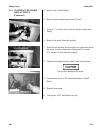
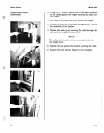
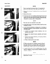
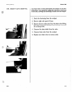
5-20. SOLENOID VALVE 7. With the bonnet assembly and core-disc assembly
Replacement (Continued) removed, disconnect the two nut fittings. One connects
the solenoid valve to the dead weight system; the other is
attached to the condensation tank.
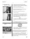
8. Remove the elbows from the solenoid valve.
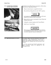
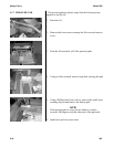
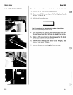
9. Remove the two adapter screws which attach the pipe
adapter to the solenoid valve body.
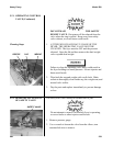
10. Remove the disc spring, guide, and Teflon seat.
11. Clean the valve body.
12. Wet “O” ring around seat with water and insert “O” ring
assembly (flat side first) in valve through “IN” side of
body. Use an eraser end of pencil and press in the Teflon
seal until it snaps into place. BE CAREFUL NOT TO
MAR OR NICK THE SEAT.
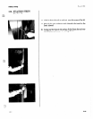
NOTE
The smallest nick can cause a pressure leak. Replace all
“O” ring seals that are in the parts kit and reassemble
valve.
13. If the complete valve is being replaced, follow steps 1, 2,
3, 4, 5, 7, and 8, in this section.
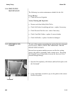
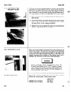
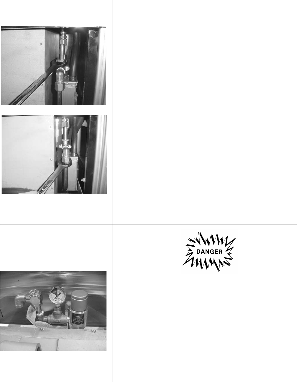
5-21. OPERATING CONTROL
VALVE
DO NOT ATTEMPT TO REMOVE THE VALVE CAP
WHILE THE FRYER IS OPERATING, or severe burns
or other injuries could result.
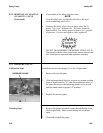
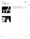
The operating valves are located at the back of the unit. The
valve left of the pressure gauge is a 14 ½ lb. safety relief valve,
and to the right of the pressure gauge, the operating valve.
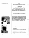
Valves are working properly, when “OPERATING ZONE”
indicates on the gauge by the pointer. The gauge pointer
should not normally exceed the operating zone. If the pressure
builds to 14 ½ lbs., the safety relief valve opens and releases
pressure from the frypot.
5-20 1200