


– 8 –
PLUMBING CONNECTIONS
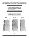
WARNING:
PLUMBING CONNECTIONS MUST COMPLY WITH APPLICABLE SANITARY, SAFETY
AND PLUMBING CODES.
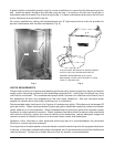
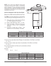
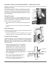
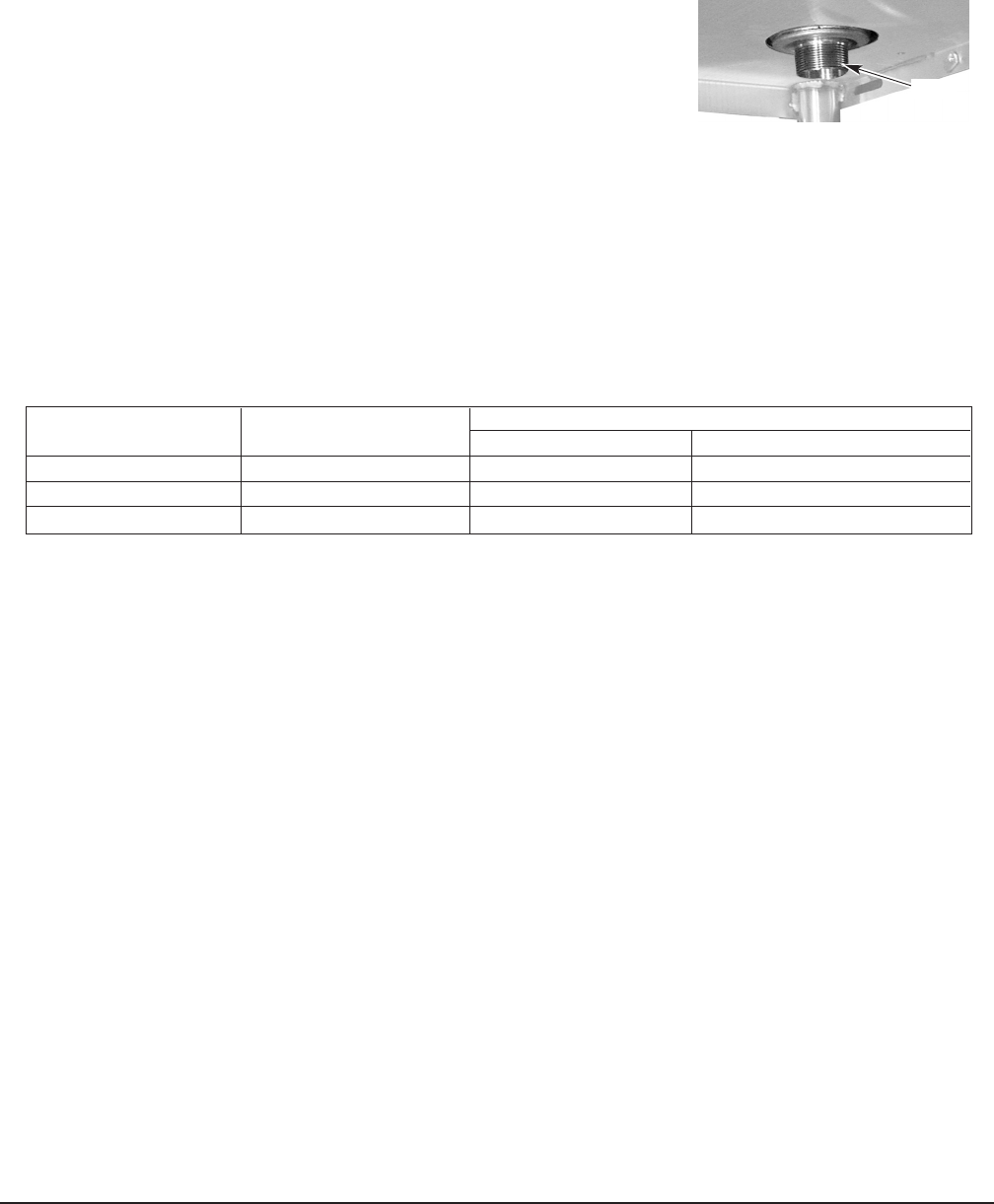
DRAIN CONNECTION
The drain connection is a 1
1
/2" externally threaded pipe connected
straight down from the bottom of the wash tank (Fig. 10). The
connection can be made in any direction by using the proper fitting
(not supplied) and routing to the appropriate drain line.
If a grease trap is required by code, it should have a minimum flow
capacity of 38 gallons per minute.
WATER CONNECTION
A suitable water hammer arrestor should be installed in the water line just ahead of the dishwasher.
Without Electric Booster Water Heater
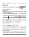
The water supply line is connected to the line strainer (top rear, Fig. 1) with
3
/4" pipe. A manual shutoff
valve and pipe union are required (not supplied).
Proper dishwasher operation requires a flowing pressure of 20 ± 5 psig at the dishwasher. If the flowing
pressure exceeds 25 psig, a pressure reducing valve (not supplied) must be installed in the water
supply line. CAUTION: The water pressure regulator must have a relief by-pass. Failure to use
the proper type of pressure regulator may result in damage to the unit.
A pressure gauge (Fig. 1) is provided (not installed) for verification of proper water pressure. The water
pressure is monitored when the solenoid valve is open and water is flowing.
With Electric Booster Water Heater
The water supply line is connected below the booster with the line strainer (supplied) and
3
/4" pipe. A
manual shut off valve and pipe union are required (not supplied).
The water supply should have a minimum temperature of 110°F, and a flowing pressure of 20 ± 5 psig
at the pressure gauge on top of the machine. If the flowing pressure exceeds 25 psig, a pressure
reducing valve (not supplied) must be installed in the water supply line. CAUTION: The water
pressure regulator must have a relief by-pass. Failure to use the proper type of pressure
regulator may result in damage to the unit.
Incoming water temperature below 110°F may require longer wash cycle time than the 57 second cycle;
refer to OPERATION, pages 17 – 18.
When the fill / final rinse valve is on, water from the booster tank enters the dishwasher through the final
rinse arms. During the rinse cycle, this water is 180°F. A small amount of water will likely dribble out
of the lower rinse arm into the tank between cycles due to the natural expansion of water as it is being
heated.
DRAIN
Fig. 10
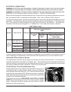
REQUIRED INCOMING WATER TEMPERATURE
Model Sanitizing Mode Water Supply
Minimum Temperature Recommended Temperature
Without Built-in Booster Hot Water Sanitizing 180°F
(82°C) 180°F (82°C)
Without Built-in Booster Chemical Sanitizing 120°F (49°C) 140°F (60°C)
With Built-in Booster Hot Water Sanitizing 110°F (43°C) 140°F (60°C)