


– 9 –
GAS TANK HEAT (When Specified)
Check the gas data plate attached to the dishwasher or the tag attached to the incoming gas piping
for the type of gas to be used.
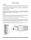
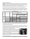
The burner is not adjustable. The maximum
flowing inlet gas pressure must not exceed
the Maximum value in the table. If line
pressure exceeds the Maximum value in
the table, an additional pressure regulator
(not supplied) must be installed in the
supply line.
Static inlet line pressure should not exceed 14" W.C. The minimum value is for input adjustment.
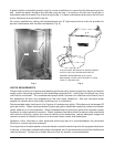
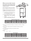
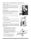
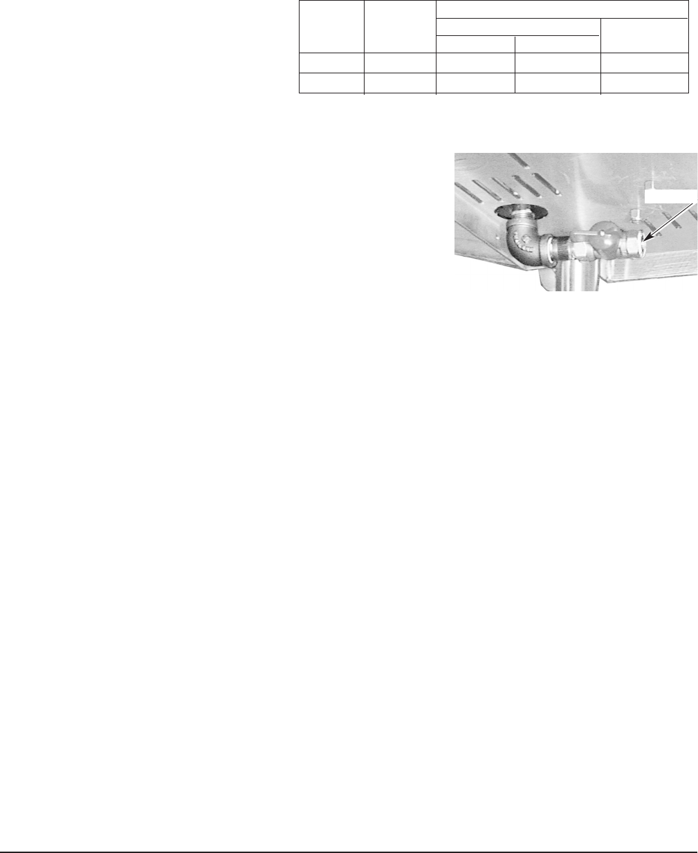
The gas valve is provided with a pressure tap to measure the gas
pressure downstream, which is also the manifold pressure. Gas
supply piping must have a sediment trap (supplied by others)
installed ahead of the dishwasher's gas control. Connect the gas
supply to the
1
/2" NPT gas inlet underneath the machine (Fig. 11).
NOTE: DO NOT use Teflon tape on gas line pipe threads. For
gas line pipe connections, use L
OCTITE 565, Hobart part 546292,
or a flexible sealant suitable for use with Natural and Propane
Gases.
The appliance and its gas connections must be leak tested before placing the appliance in operation.
Use soapy water for leak test. DO NOT use open flame. The installation must conform with local codes,
or in the absence of local codes, with the National Fuel Gas Code, ANSI Z223.1 (latest edition). Copies
may be obtained from American Gas Association, Inc., 1515 Wilson Boulevard, Arlington, VA 22209.
The appliance and its individual shutoff valve must be disconnected from the gas supply piping system
during any pressure testing of that system at test pressures in excess of
1
/2 psig (3.45kPa).
The appliance must be isolated from the gas supply piping system by closing its individual manual
shutoff valve during any pressure testing of the gas supply piping system at test pressures equal to or
less than
1
/2 psig (3.45kPa).
Dissipate test pressure from the gas supply line before re-connecting the appliance and its manual
shutoff valve to the gas supply line. Caution: Failure to follow this procedure may damage the gas
valve.
The dishwasher must be installed so that the flow of combustion and ventilation air will not be
obstructed. Do not store material underneath the machine; air openings into the combustion chamber
must not be blocked. Make sure there is an adequate supply of make-up air in the room to allow for
combustion of the gas at the burner.
Keep the appliance area free and clear from all combustible substances. Do not obstruct the flow of
combustion and ventilation air. The dishwasher must have a minimum clearance from combustible
construction of 1 inch from the flue at the rear. Clearances of 20 inches out from the dishwasher at
the front (or left side in a corner installation) by 27 inches above the finished floor and 15 inches out
from the dishwasher at the right side by 27 inches above the finished floor must be provided for
servicing.
The burner is ignited automatically by solid state electronic circuitry; there is no pilot light. Gas flow
is regulated by the temperature control circuit.
Fig. 11
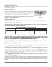
GAS PRESSURE SPECIFICATION
[FLOWING GAS PRESSURE — NOT STATIC]
Type Inches W.C. (Water Column)
FLOWING
of BTU/HR Incoming Line Pressure Manifold
Gas Minimum Maximum Pressure
Natural 25,000 3.5 7.0 3.2
Propane 25,000 9.0 11.0 8.2
GAS INLET