


– 4 –
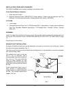
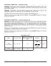
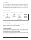
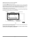
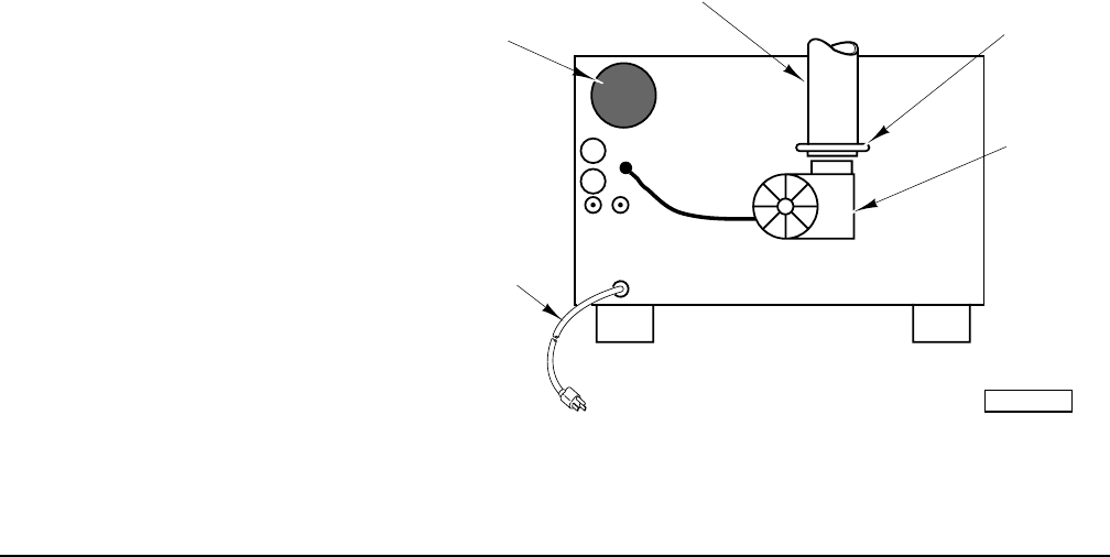
Fan
Flexible Duct
(By Others)
OVEN REAR
Power Cord
Duct Clamp
(By Others)
Blower
PL-53483
INSTALLATION CODES AND STANDARDS
The HFB6
Flash
Bake oven must be installed in accordance with:
In the United States of America:
1. State and local codes.
2. National Electrical Code, ANSI/NFPA-70 (latest edition). Copies may be obtained from The
National Fire Protection Association, Batterymarch Park, Quincy, MA 02269.
In Canada:
1. Local codes.
2. Canadian Electrical Code, Part 2, CSA Standard C22.1 (latest edition). Copies may be obtained
from The Canadian Standard Association, 178 Rexdale Blvd., Rexdale, Ontario, Canada
M9W 1R3.
ASSEMBLY
Install the upper lamp shield into the oven cavity. Be sure the shield is pushed all the way back and
is lying flat in the channels. Refer to REMOVING AND INSTALLING THE TOP LAMP SHIELD, page
13.
Place the grill on the rollers.
EXHAUST DUCT INSTALLATION
A length of flexible exhaust duct may be attached to the oven to vent hot air out of the area. Attach
the duct to the blower assembly (Fig. 1).
The other end of the duct can be vented into an existing hood, or to the outside in a manner consistent
with local building codes.
The exhaust duct must not be less
than 4" (
10.1 cm) diameter, and a
recommended maximum length of 6
feet (
182.9 cm). The duct should be
made of metal, suitable for high
temperature use. Be sure there are
no bends in the duct that will restrict
air flow.
A duct longer than 6 feet (
182.9 cm)
may require a supplementary
exhaust system to ensure adequate
air flow. The exhaust system must
support 135 cfm.
Fig. 1