


– 8 –
VENTILATION
Ventilation requirements will vary with each installation and must comply with applicable portions of the
National Fire Protection Association Standard
#96 and with local codes.
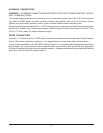
Exhaust Fan Interlock
A connection point (maximum 5-amps) is provided for Indirect Vent (Exhaust Hood) or optional Direct
Vent (Draft Hood). It is located behind the right side service panel adjacent to the 120 V power
connection. Consult local codes for vent interlock requirements.
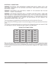
Indirect Vent (Under Exhaust Hood) - Standard
Locate the oven under an exhaust hood with adequate overhangs and exhaust rates to completely
capture the byproducts of combustion discharged from the flue. From the termination of the flue to the
filters of the hood venting system, a minimum clearance of 18" must be maintained. The hood exhaust
fan can be electrically interlocked with the oven.
Information on the construction and installation of ventilating hoods may be obtained from the standard
for
Vapor Removal from Cooking Equipment
, NFPA No. 96 (latest edition), available from the
National
Fire Protection Association
, Batterymarch Park, Quincy, MA 02269.
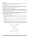
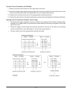
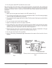
Direct Vent (Draft Hood) - Optional
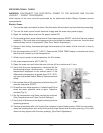
1. Remove the four screws from the tabs that secure the flue-fan grille to the top of the oven and
remove the grille covering the fan and flue.
2. Bend the four exposed tabs verticaly and secure the draft diverter to the oven flue collar with the
four screws.
3. Move the oven into position and connect customer-supplied exhaust ducting to the draft diverter
(Fig. 1).
4. Verify that the air is being drawn into the bottom of the draft diverter while the burner is firing, using
a draft gauge or smoke test.
5. Using a draft gauge, verify that a draft between 0.03" and 0.11" W.C. is maintained at a point 6"
above the draft diverter’s upper collar. Any exhaust fan or draft inducer used to maintain system
suction must be operating when oven is turned on. (See External Fan Control Connection.)
Fig. 1