PW-6000 Installation
Product Overview
PW-6000 Installation Guide, Document 800-00005, Revision A 5
Customer shall not copy the design of any of the Products or use or cause to be used
any Product design or related materials for its own benefit or for the benefit of any
other party. The covenants contained in this section shall remain effective throughout
the term of this Agreement and thereafter unless specifically waived by Honeywell
Integrated Security in writing.
2 Product Overview
The Intelligent Controller is the heart of the PW-6000 and provides the real time
processing for the connected I/O interfaces.
The PW-6000 is designed to operate without the need for a PC. It can be connected to
a Pro-Watch host computer using direct serial communication, dial-up modem, or
TCP/IP network connection. The PW-6000 holds the database for the subsystem
configuration and card holders, and the event log buffer, which is in battery-backed
memory.
Note: Please refer to the Pro-Watch Software Suite Guide for details on using the
Pro-Watch interface.
2.1 PW-6000 and PW-5000
• The PW-6000 controller configuration and operation is similar to the PW-5000
controller; both use the Pro-Watch at the front end.
• You can use the PW-5000 controller interface to configure the PW-6000
hardware settings.
2.2 Port Settings
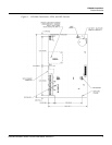
• Port 0 provides the host-embedded Ethernet interface.
• Port 1 is for RS-232 or RS-485 2-wire serial interface connections. An
optional Lantronix CoBox-Micro interface daughter board
(10Base-T/100Base-TX) is also supported on Port 1.
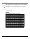
• Ports 2 and 3 are for RS-485 2-wire downstream support for connecting 32
I/O devices. Note that the I/O communications must be mapped differently in
Pro-Watch, according to the following table:
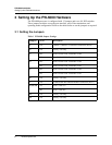
See Table 1 'PW-6000 Jumper Settings' on page 8 for more information on how to
configure the port settings.
PW-6000 Port Pro-Watch Port
24
36


