


14 www.honeywell.com
PW-6000 Installation
Setting Up the PW-6000 Hardware
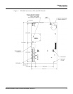
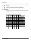
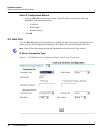
3.6 Communications Wiring
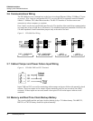
The PW-6000 processor communicates to the host via on-board Ethernet 10Base-T/100Base-TX port
or on port 1. Port 1 may be configured as RS-232, two-wire RS-485 or optional Lantronix Ethernet
10Base-T/ 100Base-TX CoBox-Micro interface. The RS-232 interface is for direct one to one
connection to a host computer, or a modem.
Ports 2 and 3 use the two-wire RS-485 interface only. The interface allows multi-drop communication
on a single bus of up to 4,000 feet (1,200 meters). Use shielded twisted pair (minimum 24 AWG) with
120-ohm impedance. Install termination jumpers only at the end-of-line unit.
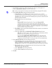
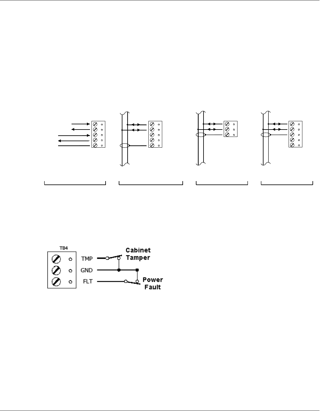
Figure 3: PW-6000 Port Wiring
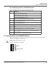
3.7 Cabinet Tamper and Power Failure Input Wiring
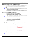
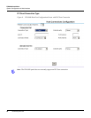
Figure 4: PW-6000 TMP and FLT Terminals
Inputs TMP and FLT are used for monitoring cabinet tamper and power failure with normally closed
contacts. These two inputs are for contact closure monitoring only; do not use end-of-line (EOL)
resistor(s). If these inputs are not used, install a short piece of wire at the input to indicate a safe
condition.
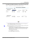
3.8 Memory and Real Time Clock Backup Battery
The event log buffer and the real time clock are backed up by a 3V lithium battery. This BR2325,
BR2330, or CR2330 battery should be replaced annually.
PORT 1 CONFIGURED
as 2-WIRE RS-485
TXD/TR+
RXD/TR-
RTS
CTS
GND
PORT 1 CONFIGURED
as RS-232
GND
TXD/TR+
RXD/TR-
RTS
CTS
PORT 2
TR-
TR+
GND
2-WIRE RS-485
PORT 3
2-WIRE RS-485
TB2 TB1
TR-
GND
TR+
GND
+12V
TB3TB3