


12 www.honeywell.com
PW-6000 Installation
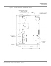
Setting Up the PW-6000 Hardware
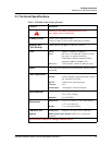
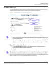
Caution: Locate the power source as close to this board as possible. Connect power with minimum of
18AWG wires.
Note: POLARITY for 12 VDC power is important. Make sure the +12 VDC is connected to the
terminal labeled +12V and the return is connected to the terminal labeled GND.
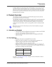
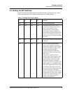
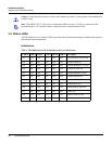
3.4 Status LEDs
The PW-6000 uses six on-board LEDs to provide status information during its initialization sequence
and normal run-time operation.
Initialization
Table 4 PW-6000 Status LED Combinations During Initialization
LED 1
LED 2 LED 3 LED 4 LED 5 LED 6 Description
ON OFF OFF OFF OFF OFF Basic processor initialization
ON ON OFF OFF OFF OFF Internal SRAM test
ON OFF ON OFF OFF OFF External SDRAM, First Chip
ON ON ON OFF OFF OFF External FLASH Test
ON OFF OFF ON OFF OFF External SDRAM, Second
ON ON OFF ON OFF OFF External SRAM Test
ON OFF ON ON OFF OFF External EEPROM Test
ON ON ON ON OFF OFF External RTC Test
ON OFF OFF OFF ON OFF Backup Battery and Reset
ON ON OFF OFF ON OFF UART Test
ON OFF ON OFF ON OFF Ethernet Interface, MII
OFF ON X X X X Final processor Initialization