


14
B. Sequence of Operation
IMPORTANT
KM-1301SAH-E utilizes a thermostatic bin control. For KM-1301SAH-E
operation, the K4 jumper (4A4883G01) must be in place on the control board
RED K4 connector or the unit will not operate.
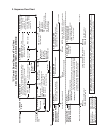
1. Sequence Cycles and Shutdown
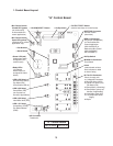
The steps in the sequence are as outlined below. When power is supplied, CB red
"POWEROK"LEDandgreen"BCCLOSED"LEDcomeon.Ifred"POWEROK"LED
is off on KM-1301SAH-E, clear ice away from the thermostatic bin control bulb in the
storagebinarea.Ifyellow"BCOPEN"LEDison,theunitwillnotstart.Inthiscase
check that CB has the K4 jumper in place on CB RED K4 connector (KM-1301SAH-E)
or clear ice away from the mechanical bin control actuator paddle in the storage bin area
(KM-1301SWH-E, KM-1301SRH-E). There is a 5-second delay before startup. Note that
the order of the component LEDs from the outer edge of CB is 1, 4, 3, 2.
a) 1-Minute Fill Cycle
LED 4 is on. WV and X2 relay (auxiliary code T-0, U-0), X11 relay (auxiliary code
U-1 and later) energize and the 1-minute ll cycle begins. After 1 minute, CB checks for
a closed F/S. If F/S is closed, the harvest cycle begins. If not, WV remains energized
through additional 1-minute ll cycles until water lls the tank and closes F/S. This serves
as a low water safety to protect PM.
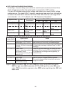
b) Initial Harvest Cycle
LEDs 1, 4, and 2 are on. WV and X2 relay (auxiliary code T-0, U-0), X11 relay (auxiliary
code U-1 and later) remain energized, HGV, X1 relay (auxiliary code T-0, U-0), X10 relay
(auxiliary code U-1 and later), Comp, and FMR energize. CB monitors the warming of the
evaporator via the thermistor located on the suction line. When the thermistor reaches
48°F (9°C), CB reads a 3.9 kΩ signal from the thermistor and turns harvest termination
over to the harvest timer (S4 dip switch 1 & 2). The harvest timer has settings of 60, 90,
120,and180seconds.Fordetails,see"II.C.2.b)HarvestTimer(S4dipswitch1&2)."
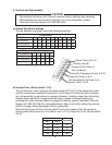
WV is energized during harvest for a maximum of 6 minutes or the length of harvest
minus 0 or 50 seconds (harvest pump timer (S4 dip switch 7)), whichever is shorter.
CAUTION! Do not adjust S4 dip switch 7 out of the factory default position on this
model. Adjustment outside of the factory default position may result in damage to
the icemaker.Fordetails,see"II.C.2.e)HarvestPumpTimer(S4dipswitch7)."LED4
goes off when WV and X2 relay (auxiliary code T-0, U-0), X11 relay (auxiliary code
U-1 and later) de-energize. LED 3 comes on and PM energizes and runs for the last 0 or
50 seconds of harvest depending on S4 dip switch 7 setting. This circulates water over
the evaporator for the last 0 or 50 seconds of harvest. PM is energized through the #5
pin (DBu wire) on the CB K1 ten-pin connector and the X1 relay (auxiliary code T-0, U-0),
X10 relay (auxiliary code U-1 and later). When the harvest timer terminates, the harvest
cycle is complete. CB checks the position of F/S and proceeds to the freeze cycle if it is
closed or calls for a 1-minute ll cycle if it is open. The minimum total time allowed by CB
for a complete harvest cycle is 2 minutes.