


35
IV. Service Diagnosis
WARNING
1. This unit should be diagnosed and repaired only by qualied service
personnel to reduce the risk of death, electric shock, serious injury, or re.
2. Risk of electric shock. Use extreme caution and exercise safe electrical
practices.
3. Moving parts (e.g., fan blade) can crush and cut. Keep hands clear.
4. CHOKING HAZARD: Ensure all components, fasteners, and thumbscrews
are securely in place after the unit is serviced. Make sure that none have
fallen into the storage bin.
5. Make sure all food zones in the icemaker and storage bin are clean after
theunitisserviced.Forcleaningprocedures,see"VI.Cleaningand
Maintenance."
A. Diagnostic Procedure
The diagnostic procedure is basically a sequence check which can be used at unit
startup or for system diagnosis. This procedure allows you to diagnose electrical system
and component failures in normal operating conditions of 70°F (21°C) or warmer air and
50°F (10°C) or warmer water temperatures. Before conducting the diagnostic procedure,
check for correct installation, proper voltage per unit nameplate, and adequate water
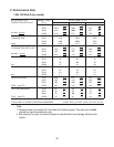
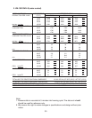
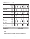
supply.CheckCBusingthestepsin"IV.B.ControlBoardCheck."Checkthedipswitch
settings to assure that S4 dip switch 3, 4, 7, 8, 9, & 10 and S5 dip switch 1 through 5 are
in the factory default position. S4 dip switch 1, 2, 5, & 6 are cleaning adjustments and
thesettingsareexible.Forfactorydefaultsettings,see"II.C.2.a)DefaultDipSwitch
Settings."Asyougothroughtheprocedure,checktoassurethecomponentsenergize
and de-energize correctly. If not, those components and controls are suspect.
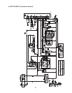
1) Turn off the power supply, then access the control box. Clear any ice from BC.
2)Turnonthepowersupply,thenmovethecontrolswitchtothe"ICE"position.A5-second
delayoccurs.CBred"POWEROK"LEDandgreen"BCCLOSED"LEDcomeon.
Ifred"POWEROK"LEDisoffonthermostaticBCunit(KM-1301SAH-E),clearice
away from the thermostatic bin control bulb in the storage bin area. If no ice is near
the thermostatic bin control bulb or the LED does not come on even after clearing
awayice,checkthermostaticBC.See"IV.C.1.ThermostaticBinControlCheck."If
yellow"BCOPEN"LEDison(indicatingafullbin),conrmthatCBK4jumperisin
place on thermostatic BC unit (KM-1301SAH-E) or check BC on mechanical BC unit
(KM-1301SWH-E,KM-1301SRH-E).See"IV.C.2.a)MechanicalBinControlCheck."
3) 1-Minute Fill Cycle – LED 4 is on. WV and X2 relay (auxiliary code T-0, U-0), X11 relay
(auxiliarycodeU-1andlater)energizeandthe1-minutellcyclebegins.After1minute,
CB checks for a closed F/S. If F/S is closed, the harvest cycle begins. If closed,
continue to step 4. If open, WV remains energized through additional 1-minute ll cycles
until water lls the tank and closes F/S (low water safety). Diagnosis: If WV does not
open, check the supply voltage at WV terminals, check continuity on the coil, conrm
the screen or external lter isn't plugged (no water ow). If unit fails to start harvest,
checkforopenF/Sorbad1-minutetimerinCB.See"IV.D.FloatSwitchCheckand
Cleaning"and"IV.B.ControlBoardCheck."