


45
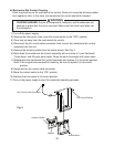
E. Thermistor Check
To check thermistor resistance, follow the steps below.
1) Turn off the power supply.
2)Removethefrontpanel,thenmovethecontrolswitchtothe"OFF"position.
3) Remove the control box cover.
4) Remove the thermistor.
5) Immerse the thermistor sensor portion in a glass containing ice and water for 2 or
3 minutes.
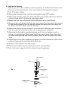
6) Disconnect the white thermistor connector from the control board WHITE K3 connector
and check the resistance between thermistor leads. Normal reading is within 4.7 to
6.2kΩ.Ifoutsidethenormalreading,replacethethermistor.See"V.B.ImportantNotes
forComponentReplacement."Ifinsidethenormalreading,continuetothenextstep.
7)Replacethethermistorinitscorrectposition.See"V.B.ImportantNotesforComponent
Replacement."
8) Reconnect the white thermistor connector to the control board WHITE K3 connector.
9) Replace the control box cover in its correct position, then turn on the power supply.
10)Movethecontrolswitchtothe"ICE"position.
11) Once the harvest cycle starts, begin timing the harvest cycle.
12) The harvest timer should terminate and end the harvest cycle within 2 to 3 minutes. If
the harvest timer does not terminate and end the harvest cycle, the harvest timer is bad
and the control board should be replaced.
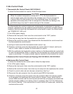
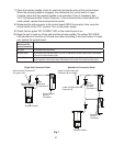
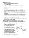
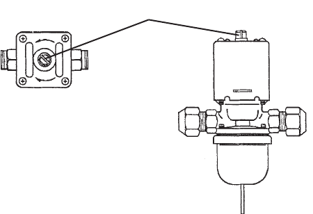
F. Adjustment of Water Regulating Valve (water-cooled model)
Thewaterregulatingvalve(alsocalled"waterregulator")isfactoryset,andgenerallyno
adjustment is required. However, when necessary, adjust the water regulator using the
following procedures.
1) Prepare a thermometer to check the condenser drain temperature. Attach a pressure
gauge to the high-side line of the system.
2) Five minutes after a freeze cycle starts,
conrm that the thermometer reads 104°F
to 115°F (40°C to 46°C). If it does not,
use a at blade screwdriver to rotate the
adjustment screw on the water-regulating
valve until the temperature is in the proper
range (rotate counterclockwise to raise
the temperature or clockwise to lower the
temperature). See Fig. 5. Next, check that
the reference pressure is in the range
indicated in the Head Pressure table in the
Performance Data section. If it is not in the
proper range, verify the refrigerant charge.
3) Check that the condenser drain temperature is stable.
Fig. 5
Adjustment Screw
CCW – Higher
CW – Lower
Top View