


36
4) Initial Harvest Cycle – LEDs 1, 4, and 2 are on. WV and X2 relay (auxiliary code
T-0, U-0), X11 relay (auxiliary code U-1 and later) remain energized, HGV, X1 relay
(auxiliary code T-0, U-0), X10 relay (auxiliary code U-1 and later), Comp, and FMR
energize.CBmonitorsthewarmingoftheevaporatorviathethermistorlocatedonthe
suction line. When the thermistor reaches 48°F (9°C), CB reads a 3.9 kΩ signal from
the thermistor and turns harvest termination over to the harvest timer (S4 dip switch
1 & 2). The harvest timer has settings of 60, 90, 120, and 180 seconds. For details, see
"II.C.2.b)HarvestTimer(S4dipswitch1&2)."Whentheharvesttimerterminates,the
harvest cycle is complete. CB checks the position of F/S and proceeds to the next cycle
if it is closed, or calls for a 1-minute ll cycle if it is open. The minimum total time allowed
by CB for a complete harvest cycle is 2 minutes.
WV is energized during harvest for a maximum of 6 minutes or the length of harvest
minus 0 or 50 seconds (harvest pump timer (S4 dip switch 7)), whichever is shorter.
LED 4 goes off when WV and X2 relay (auxiliary code T-0, U-0), X11 relay (auxiliary
code U-1 and later) de-energize. LED 3 comes on and PM energizes and runs for the
last 0 or 50 seconds of harvest depending on S4 dip switch 7 setting. CAUTION! Do
not adjust S4 dip switch 7 out of the factory default position on this model.
Adjustment outside of the factory default position may result in damage to the
icemaker. Fordetails,see"II.C.2.e)HarvestPumpTimer(S4dipswitch7)."
PM is energized through the #5 pin (DBu wire) on the CB K1 ten-pin connector and
the X1 relay (auxiliary code T-0, U-0), X10 relay (auxiliary code U-1 and later). When
the harvest timer terminates, the harvest cycle is complete. CB checks the position of
F/S and proceeds to the next cycle if it is closed or calls for a 1-minute ll cycle if it is
open.TheminimumtotaltimeallowedbyCBforacompleteharvestcycleis2minutes.
Diagnosis: Check if Comp is running, HGV and WV still energized. Average harvest
cycle at factory setting is 2 to 3 minutes. How long does initial harvest last? 1.5 minutes
after initial harvest begins, touch Comp discharge line. Is it hot? If not, check refrigerant
pressures and Comp operation. If it is hot, touch the inlet line to the evaporator. Is it
hot? If it is hot and the freeze cycle is not starting, check the harvest timer adjustment
(S4 dip switch 1 & 2), the thermistor for open circuit, the discharge line temperature,
Compefficiency,andifHGVisfullyopen.Forathermistorcheck,see"IV.E.Thermistor
Check."CheckthatPMcirculateswateroverevaporatorforthelast50secondsof
harvest. If not, check X1 relay (auxiliary code T-0, U-0), X10 relay (auxiliary code
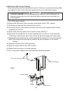
U-1andlater)andS4dipswitch3&4.If1-minutellcyclestarts,see"IV.D.Float
SwitchCheckandCleaning."
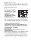
5) Freeze Cycle – LED 1 is on. Comp and FMR remain energized, PM energizes
or remains energized depending on harvest pump timer (S4 dip switch 7) setting.
FM and LLV energize. HGV and X1 relay (auxiliary code T-0, U-0), X10 relay (auxiliary
code U-1 and later) de-energize. The unit is held in freeze by a 5-minute short cycle
protection timer (CB will not accept a signal from F/S). After the 5-minute short
cycle protection timer terminates, CB turns freeze termination over to F/S. During
the rst 5 minutes of freeze, conrm that the evaporator temperature drops. After
5 minutes in freeze, disconnect black F/S connector from CB BLACK K5 connector.
After a 15 second delay, the unit should switch out of the freeze cycle. Diagnosis: If
the evaporator is not cold, check to see if HGV is still open or if TXV is not opening
properly, if WV is continuing to ll the reservoir, if there are improper unit pressures,