


18
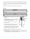
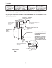
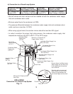
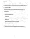
b) Connection to a Closed Loop System
Condenser Water
Supply Inlet
Minimum Condenser
Water Supply Line Size
Condenser
Return Outlet
Minimum Condenser
Return Line Size
1/2" Female Pipe
Thread (FPT)
1/4" Nominal ID Copper
Water Tubing or Equivalent
1/2" Female Pipe
Thread (FPT)
1/4" Nominal ID Copper
Water Tubing or Equivalent
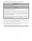
• Shut-off valves and drain valves must be installed at both the condenser water supply
inlet and condenser return outlet.
• Minimum water fl ow to the condenser is 4 GPM.
• The pressure differential between the condenser water supply inlet and condenser return
outlet must be no less than 10 PSIG.
• When using a glycol blend, the solution mixture should be less than 30% glycol.
• In order to maintain the proper high side pressure, the condenser water supply inlet
temperature must be in the 45°F to 90°F (7°C to 32°C) range.
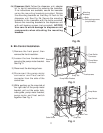
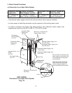
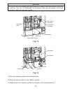
KMD-410MWH
Connection to a Closed Loop System
Fig. 11
Icemaker Water
Supply Inlet
1/2” FPT
Icemaker Drain
Outlet
3/4” FPT
Icemaker Water Supply Line
Shut-Off Valve
Icemaker Water Supply Line
Drain Valve
Bin Drain Outlet
3/4” FPT
Bin
Icemaker
Condenser Water
Supply Inlet
1/2” FPT
Condenser
Return Outlet
1/2” FPT
Condenser Water Supply Line
Shut-Off Valve
Condenser Water Supply Line
Drain Valve
2-inch
(5-cm)
air gap
Drain
Floor
Minimum 1/4” Nominal ID
Copper Water Tubing
Minimum 3/4” Nominal ID
Hard Pipe
Vent Tube
Condenser Return Line
Shut-Off Valve
Condenser Return Line
Drain Valve
Be sure there is suffi cient extra
water supply line and drain line
for the appliance to be pulled
out for service.
Separate piping to approved
drain. Leave a 2-inch (5-cm)
vertical air gap between the
end of each pipe and the drain.