


25
0713
‘
2. Close Beverage Control Panel Assembly water
inlet supply line shutoff valve.
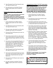
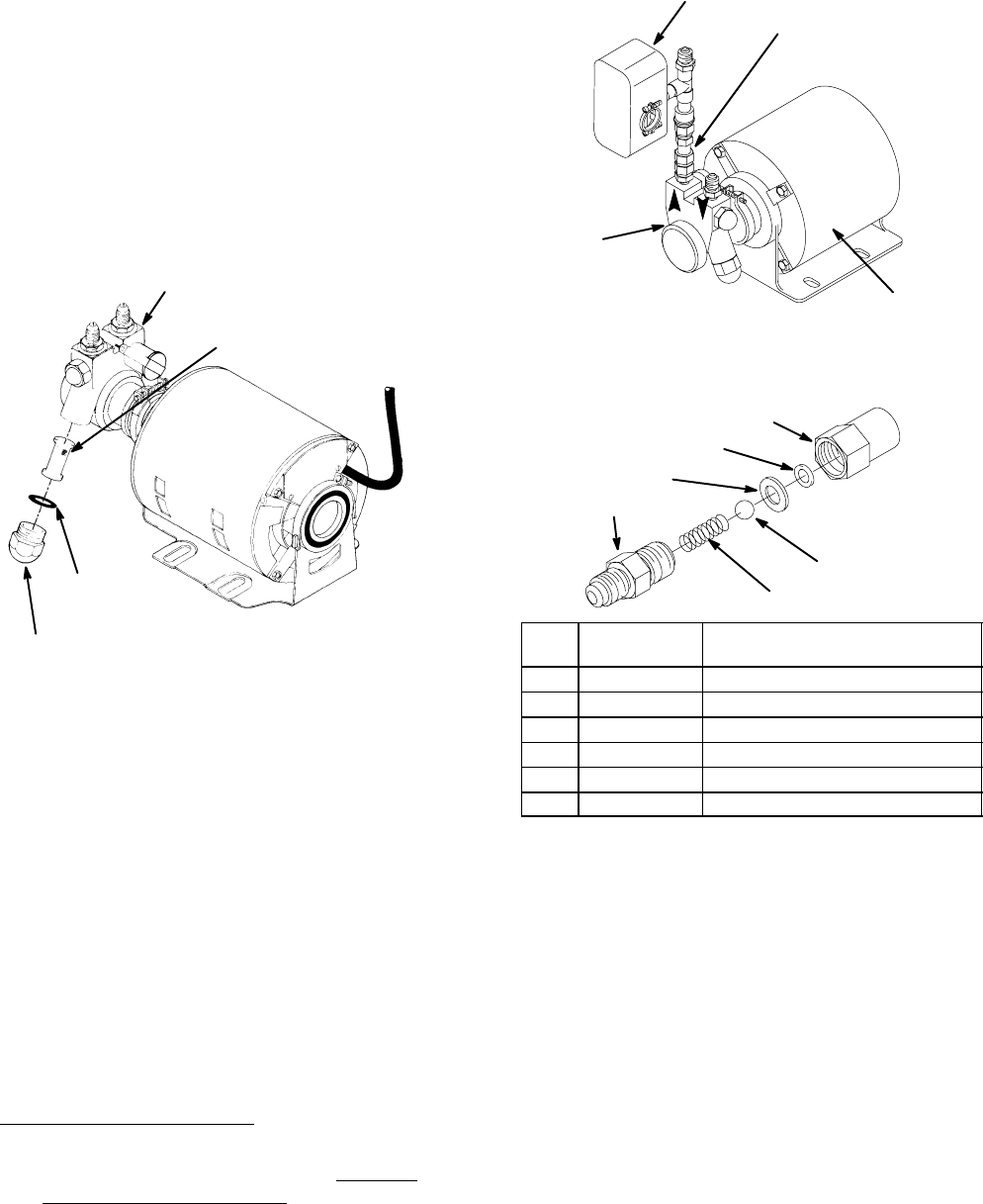
3. Loosen screen retainer, then pull screen retainer
and strainer screen from water pump. (see
Figure 12).
4. Pull strainer screen from screen retainer. Clean
any sediment from screen retainer and pump
screen retainer port.
WATER PUMP
O–RING
(P/N 315349–000)
SCREEN RETAINER
WATER
STRAINER SCREEN
(P/N 315348–000)
FIGURE 12. WATER STRAINER SCREEN
5. Inspect strainer screen for holes, restrictions,
corrosion, and other damage. Discard damaged
strainer screen.
6. Check O–Ring on screen retainer. Replace worn
or damaged O–Ring (P/N 315349–000).
NOTE: A strainer screen should always be used,
otherwise particles could foul liquid check valve.
7. Install good or new strainer screen (P/N
315348–000) in screen retainer, then screw
retainer into water pump and tighten securely.
8. Service liquid check valve (refer to next
paragraph, Servicing Liquid Check Valve).
Servicing Liquid Check Valve
1. Service water pump water strainer screen as
instructed in previous paragraph, Servicing
Water In let Strainer Screen; before servicing
liquid check valve.
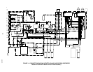
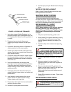
2. Disconnect pressure switch (see Figure 13) from
liquid check valve assembly outlet, then remove
check valve from water pump outlet. Retain
white tapered gasket inside inlet (female) end of
check valve.
PRESSURE
SWITCH
LIQUID CHECK
VALVE
WATER
PUMP
MOTOR
FIGURE 13. WATER PUMP AND MOTOR
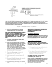
1
2
3
4
5
6
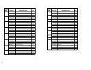
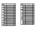
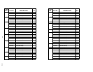
Index
No.
Part
No.
Name
1 317963 Housing
2 312415 Flat Washer, Stainless Steel
3 *312418 Ba;; Seat (quad ring)
4 312419 Ball
5 312196 Spring
6 317965 Retainer
*Install new ball seat at each servicing.
FIGURE 14. LIQUID CHECK VALVE ASSEMBLY
3. Disassemble each check valve as shown in
Figure 14
4. Wipe each part with clean lint–free cloth. Inspect
each part, especially ball for burrs, nicks,
corrosion, deterioration, and other damage.
Discard ball seat and any damaged or suspicious
parts and replace with new parts when
reassembled.
5. Reassemble check valve as shown in Figure 14.
ALWAYS INSTALL NEW BALL SEAT
(QUADDING) P/N 312418–000.
6. Make sure white tapered gasket is in place
inside female end of check valve assembly, then
install check valve assembly on fitting in water
pump outlet port.
7. Connect pressure switch to check valve
assembly outlet.