


7
0713
A. Locate two full CO
2
cylinders in upright
positions next to the CO
2
mounting
bracket. Fasten CO
2
cylinders with safety
chain.
B. Connect two CO
2
lines from Beverage
Control Panel Assembly two primary CO
2
regulators to the CO
2
cylinders.
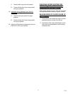
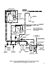
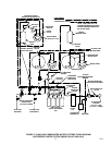
7. Installation employing the Optional Water
PressureBooster System Kit (see applicable
Figure 3, 4, 5, or 6)
Note service valve on bottom of the Water Pressure
Booster System Water Tank. The water tank must be
pressurized with 40 5–PSI (2.76 .34 Bars) of
commercially dry air, CO
2
, or nitrogen gas through
the water tank service valve before putting system
into operation.
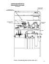
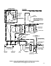
8. Water Surge Tank (see applicable Figure 3, 4,
5,, or 6)
Note service valve on bottom of the water surge
tank. The water surge tank must be pressurized with
12 2–PSI (.83 .14 Bars) of commercially dry air,
CO
2
, or nitrogen gas through the water tank service
valve before putting system into operation.
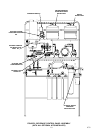
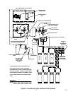
9. System Connected to Bulk CO
2
Supply (see
Figure 7)
A. Open shutoff valve on bulk CO
2
tank.
B. Adjust CO
2
regulator on bulk CO
2
tank to
105–PSI (7.24 Bars). Pull up on
carbonators tanks relief valves for
approximately two seconds to bleed air
from tanks.
C. Adjust sugar–base syrup tanks CO
2
regulator with 100–PSI (6.9 Bars) gauge on
secondary CO
2
regulator assembly to
60–PSI (4.14 Bars).
D. Adjust diet syrup tank CO
2
regulator with
30–PSI (2.07 Bars) gauge on secondary
CO
2
regulator Assembly to 12–PSI (.83
Bars).
10. System connected to two fifty pound CO
2
cylinders (see Figure 7).
A. Open CO
2
cylinders valves slightly to allow
lines to slowly fill with gas, then open
valves fully to back seat valve.
Back–seating valve prevents leakage
around valve shaft.
B. Adjust two Primary CO
2
regulators to
105–PSI (7.24 Bars). Pull up on
carbonator(s) tank(s) relief valve(s) for
approximately two seconds to bleed air
from tanks.
C. Adjust secondary CO
2
regulator assembly
CO
2
regulator with 100–PSI (6.9 Bars)
gauge for sugar–base syrup tanks to
60–PSI (4.14 Bars).
D. Adjust diet syrup tank CO
2
regulator with
30–PSI (2.07 Bars) gauge on secondary
CO
2
regulator assembly to 12–PSI (.83
Bars).
11. The Post–Mix Dispenser(s) and entire syrup
systems should be sanitized as instructed in
manual(s) provided with Dispenser(s) before
syrup is connected into the systems.
IMPORTANT: Even though sanitizing procedure
has been performed on syrup systems during
initial installation a temporary new tubing plastic
off–taste of dispensed product may occur. If this
off–taste should occur, prepare a solution of
citric acid in proportion as instructed on the
citric acid packaging. Pump citric acid solution
through the syrup systems and all carbonated
and plain water tubes installed as part of the
system. Thoroughly flush syrup systems and all
carbonated and plain water tubes with plain
water to make sure all citric acid has been
removed.
12. Open all plain water shutoff valves on Beverage
Control Panel Assembly.
13. Check entire system for syrup, CO
2
gas, and
plain and carbonated water leaks. Repair if
leaks are evident.
14. Plug carbonator(s) and Water Pressure Booster
system (if applicable) power cords into electrical
outlets.
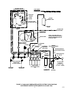
15. If Optional Air Compressor Kit is being used and
it is desired to operate with compressed air
rather than CO
2
gas pressure.
A. Plug air compressor power cord into
electrical outlet.
B. Place CO
2
/air switchover valve (see Figure
7) in air position.
16. Refer to manual(s) provided with the
Dispenser(s) to put Dispenser(s) into operation.
Operate all dispensing valves to bleed all air
from plain and carbonated water systems.
17. Standard Installation Connected to Bulk Syrup
Tanks (see Figure 7)