


5
0713
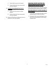
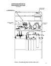
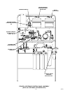
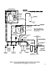
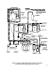
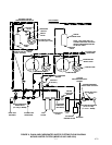
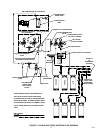
6. Connect one end of TUBE ASS’Y (item 33) to
water surge tank elbow assembly 3/8–inch flare
(5/8–18) fitting as shown in applicable Figure 3,
4, 5, or 6. Seal connection with TAPERED
GASKET, BLACK (item 4).
7. Connect other end of tube assembly to water
manifold assembly 3/8–inch flare (5/8–18) fitting
on water filter assembly (see applicable Figure
3, 4, 5, or 6). Seal connection with TAPERED
GASKET, BLACK (item 4).
FASTENING BEVERAGE CONTROL
PANEL ASSEMBLY TO WALL
WARNING: The Beverage Control
Panel Assembly must be securely
fastened to the wall before
connecting the assembly into the system.
The Beverage Control Panel Assembly must
be fastened to the wall with six fasteners
provided by the Installer) and each fastener
must be capable of resisting a 200 pound
(90.7 KG) pull. Be very careful when handling
the assembly as it is very top heavy and
could fall and cause serious personal injury
and also equipment damage.
Refer to instructions in previous WARNING note and
secure Beverage Control Panel Assembly to wall as
follows:
1. Very carefully, lay panel assembly upper frame
over on its back side. Slide telescoping lower
frame up on panel assembly upper frame.
2. Very carefully, lift Beverage Control Panel
Assembly up and place in position up against
wall.
3. Using screw adjusters on bottoms of Legs,
adjust until Control Panel Assembly sits level.
4. Secure Control Panel Assembly to wall with six
fasteners provided by the installer.
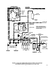
5. Using .156 I.D. tubing provided in installation kit,
connect one end of tubing to vented double
check valve (see applicable Figure 3, 4, 5, or 6),
then route other end of tubing to a permanent
floor drain.
6. Fasten tubing to frame assembly with wire ties
provided in installation kit.
CONNECTING SUGAR–BASE SYRUP TANKS
CO
2
LINES TO BEVERAGE CONTROL
PANEL ASSEMBLY CO
2
MANIFOLD
(see Figure 7)
1. Using .265 I.D. tubing, fittings, gas quick
disconnects, and tubing clamps, provided in the
installation kit, make up three gas lines to be
connected between the CO
2
manifold and the
sugar–base syrup tanks.
2. Connect three gas lines swivel nut ends to CO
2
check valves on Beverage Control Panel
Assembly CO
2
manifold. Seal connections with
white tapered gaskets.
CONNECTING DIET SYRUP TANK CO
2
LINE
TO BEVERAGE CONTROL PANEL
ASSEMBLY DIET SYRUP CO
2
REGULATOR.
(see Figure 7)
3. Using .265 I.D. tubing, fittings, gas quick
disconnect, and tubing clamps, make up one
gas line to be connected between the Beverage
Control Panel Assembly diet–syrup tank.
4. Connect swivel nut end of gas line to check
valve on outlet of the diet–syrup tank CO
2
regulator. Seal connection with white tapered
gasket.
CONNECTING BEVERAGE CONTROL
PANEL ASSEMBLY TO POST–MIX
DISPENSER(S) AND OTHER EQUIPMENT TO
BE CONNECTED TO THE SYSTEM
(see Figure 7)
NOTE: The syrup, plain and carbonated water
and CO
2
lines to the Post–Mix Dispenser(s) and
various other equipment at the installation site
may be routed overhead or through a floor chase
from the Beverage Control Panel Assembly.
MAKE SURE ALL LINES ARE LABELED FOR
IDENTIFICATION.
Refer to manual(s) provided with the Post–Mix
Dispenser(s) to connect plain water, carbonated
water, and syrup lines to the Dispenser(s).
Center–Island Installation with Optional Syrup Tanks
Hookup (see Figure NO TAG)
Connect CO
2
, plain water, carbonated water, and
syrup lines between Beverage Control Panel
Assembly, the Post–Mix Dispenser, and other
equipment to be connected to the system. Optional
syrup tanks Kit (P/N 0673) is used to connect four
syrup tanks into system.
Connect insulated plain water line between plain
water line connected to Post–Mix Dispenser cold
plate and the Orange Juice Dispenser.