


Millennium II 6000 Installation Manual
Publication Number: 620919546INS - 2 - © 2003-2004, IMI Cornelius Inc.
INSTALLATION
RECEIVING & UNPACKING
1. Inspect the carton and note any damage, regardless if it appears minor. If the carton is damaged,
note on the consignee copy of the freight invoice “exterior carton damage – concealed damage pos-
sible”.
2. Cut the banding strap and remove the exterior carton sleeve, internal fillers and plastic bag around
the dispenser. Carefully inspect for damage.
NOTE: IMI Cornelius is not responsible for damaged freight. If damage is found, you must save
all packaging material and contact the freight carrier. Failure to contact the carrier within 48 hours
of receipt may void your claim.
INSTALLATION
1. Typically the dispenser is placed directly on the counter and a food grade silicone sealant is applied
around the base. However, the legs that are included with the dispenser may be used. The follow-
ing instructions assume the legs will not be used.
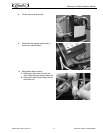
2. Depending on the type of counter, it may be necessary to provide access through the counter at the
rear of the dispenser for the drain, power, water and concentrate connections.
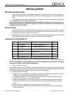
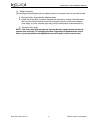
Installation Kit P/N 629087473
3. With the assistance of another person, lift the dispenser using the base and place it on the counter.
NOTE: The dispenser is extremely heavy when operational. Make certain the counter can support
a minimum of 300 lbs. directly below the dispenser.
4. Sanitizing Prior to Initial Use
The beverage system must be cleaned and sanitized after installation is completed to safeguard against
any possible contaminants that may have entered the system during transport or installation. Refer to the
“Cleaning and Sanitizing the System” section of this manual for procedures.
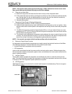
5. Connecting the Water Supply
A. Water Pipe Connections and fixtures directly connected to a potable water supply shall be sized,
installed and maintained according to federal, state and local laws.
B. It is recommended that a 1/2” OD copper supply line with a shut–off valve and water filter be
located within 3–6 feet (.9–1.8 m) of the dispenser.
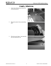
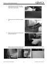
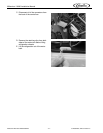
C. Remove the splash panel. Run the water supply line through the hole in the back of the base
marked “water” and up the front of the unit to the water inlet fitting located behind the splash
panel.
D. Connect the 3.8” ID supply line to water supply with a 3/8” barb fitting.
E. When installing the splash panel, attach the ground wire, at the water bath front, to the splash
panel grounding tab.
Item Part Number Description Qty.
1 300423000 Connector Bag-N-Box 375 6
2 31525016 O-Ring 614ID 070CS 1
3 50119 Hose Plastic 5.8ID X 1/8 Wall 5 ft.
4 70339 Clamp Hose 1
5 620919546INS Manual Installation Millennium 6V 1
6 620920205 thru 10 Flavor Strip Assorted #1 thru #6 6