


Millennium II 6000 Installation Manual
© 2003-2004, IMI Cornelius Inc. - 3 - Publication Number: 620919546INS
NOTE: The dynamic water pressure must be 20 psig (1.3 Bar) minimum to ensure correct valve
flow control and must not exceed 100 psig to avoid valve damage.
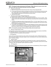
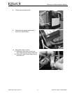
6. Filling the Ice Water Bath
A. Remove the top panel and locate the filler hole in the top of the refrigeration deck.
B. Fill the water bath with cool water until it begins to trickle out of the overflow tube and into the drip
tray. Use tap water. Do not use distilled water as it’s purity has very low electrical conductivity.
This can degrade performance of the electronic ice bank control.
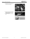
C. Reinstall the top panel.
7. Connecting Power Supply & Starting Refrigeration
A. Plug the power cord into a 115VAC 15 Amp grounded receptacle.
B. Place the rocker switch and key switch, both located on the top panel, to the “on” position. Note
that the rocker switch controls power to the dispenser and the key switch controls the pumps and
valves.
C. The Millennium forms an ice bank of approximately 25 lbs. (11.4 kg) in about 5 hours at a room
temperature of 75
o
F (24
o
C). Once the ice bank has grown to the proper size, the ice bank control
will shut down the refrigeration circuit.
D. The ice bank control operates the compressor and condenser fan motor to control the size of the
ice bank. The control board will not start or re–start the compressor until after the compressor has
been off for at least 3 minutes to all refrigeration system pressure to equalize.
NOTE: It is normal to see water trickle from the overflow as the ice bank forms.
8. Electronic Control Board Function
An integrated circuit board and microprocessor are used to control the electrical functions of the Millen-
nium beverage dispenser. Functional features of the control board include:
• Ice bank control with compressor start-up protection
• LED diagnostics
Inputs to the control board include line power and the ice bank position sensor. Switched outputs from
the circuit board include the compressor, agitator motor, and condenser fan motor (refer to electrical dia-
gram in reference section).
9. Ice Bank Control
The ice bank control operates the compressor and condenser fan motor to control the size of the ice
bank. The control board will not restart the compressor until after the compressor has been off for at least
3 minutes to allow the refrigeration system pressures to equalize.
10. LED Diagnostics
LED diagnostic lights are mounted on the control board to assist in troubleshooting. There is one green
LED and one red LED.
Red LED
Green LED