28
166240004
12/1/94
Rev 3/4/96
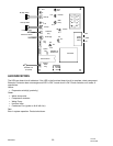
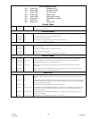
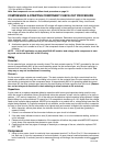
Check for supply voltage from circuit board, lead connections to contactor coil, and ohms value of coil.
* (3) if the product is 3 phase
Note: See compressor run-on condition check procedure on page 31.
COMPRESSOR & STARTING COMPONENT CHECK-OUT PROCEDURE
When compressors fail to start or run properly, it is normally the external electrical supply or the compressor
start components that are defective – the overload protector, start and/or run capacitor, relay, circuit board,
safety controls, etc.
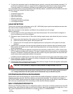
1. Check voltage at compressor terminals. NO voltage will require checking the electrical circuit working back
from the compressor to determine where the voltage supply is interrupted and correct as required. The
load voltage, while compressor is trying to start, should not be less than 90% of rated required voltage.
Line voltage and wire size effect the life expectancy of the electrical components, compressor, motor winding,
solenoid coils, etc.
Poor line quality voltage will cause many erratic electrical problems. Remember every electrical product, ice ma-
chine, dispenser, walk-in, reach-in, air conditioner, etc. required proper power supply to operate. Be certain
when voltage checks are performed that you are measuring load voltage, not line voltage.
2. A defective capacitor or start relay may prevent the compressor from starting. Should the compressor at-
tempt to start, but is unable to do so, or if the compressor hums or trips off on the over protector, check the
following:
NOTE: For 50 HZ application on dual rated 50/60 HZ models, load voltage while compressor is start-
ing must not be less than 90% of 50 HZ rating.
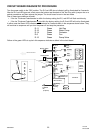
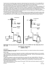
Relay
Potential –
For the potential type, contacts are normally closed. The start contacts open by C.E.M.F. generated by the com-
pressor at approximately 80% of the normal operating speed. As the contacts open, only the start capacitor is
removed from the start circuit. Both the start and run winding and the run capacitor remain in the circuit. This
relay may or may not be directional in mounting.
Current –
For the current type, contacts are normally open. The start contacts close by the high current draw from the
locked rotor condition with only the run winding in the circuit. As the contacts close, the start capacitor and the
start winding is energized and the compressor starts. At approximately 80% of its operating speed the current
draw drops off, the relay contacts open removing the start winding and start capacitor from the circuit. (Remem-
ber, current relays are directional in their mounting to allow contacts to lift and close).
Capacitors
A quick check is to replace suspected defective capacitors with known good capacitors being careful to stay
within the range for substitute values. Should those values be unknown, a basic rule for capacity is: for start ca-
pacitors 10% and run capacitors 5% of the rating on the defective original capacitor being replaced. Voltage
should always try and be matched; if it cannot be, it is acceptable to increase up to 10% higher than the voltage
listed on the capacitor being replaced. NEVER put a capacitor on a product with a voltage rating lower than the
original being replaced. If a capacitor analyzer is not available, an ohm meter may be used to check a capacitor
for short or open circuits. Set the ohm meter to its highest scale and connect its leads to the capacitor terminals.
1. With a capacitor, without plate defect, the indicator should first move to zero (0) and then gradually in-
crease to infinity.
2. If there is no movement of the ohm meter indicator, an open circuit is indicated.
3. If the ohm meter indicator moves to zero (0) and remains there, or on a low resistance reading, a short cir-
cuit is indicated.
4. Please note this check does not determine if the capacitor will deliver the proper rated MFD/UFD required,
it only shows if the capacitor has shorted or open circuits.
5. Capacitors that show any signs of leakage of electrolyte, or damage of the can, should be replaced. DO
NOT TEST!
Compressor
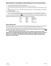
1. Using an ohm meter, check for continuity from compressor terminal C to R and C to S. If the compressor is
hot, wait one (1) hour for compressor to cool and recheck. An open internal overload protector can cause a
lack of continuity. If continuity cannot be measured through all windings, the compressor must be replaced.


