


UF-1 and UFB-1 Valves Training Manual
- 16 - © 1999-2005, IMI Cornelius Inc.
INSTALLATION
CAUTION — Only trained and certified technicians should service this
unit. ALL WIRING AND PLUMBING MUST CONFORM TO
NATIONAL AND LOCAL CODES.
1. INSTALLATION REQUIREMENTS
1.1 Requirements Summary
The beverage dispenser that the UF-1 or UFB-1 valve(s) will be installed on should
be capable of supplying an adequate flow of water (for the beverage and for cool-
ing) and syrup.
environment: . . . . . . .indoor installation only
temperature: . . . . . . . .50 to 110° F ambient temperature
syrup BIB: . . . . . . . . .60 to 80 psi
carbonated water:. . . .65 to 110 psi
plain water:. . . . . . . . .50 to 110 psi
electrical: . . . . . . . . . .24 volts AC (22-27 volts), 80 VA, 50/60 Hz
1.2 Electrical Requirements
Before connecting electrical power to the beverage dispenser refer to nameplate to
see if it requires 50 or 60 Hz power.
DANGER — To avoid possible serious injury or death the ELCB (earth leakage
circuit breaker) must be installed in the electrical circuit of all 50 Hz units.
WARNING — To avoid possible electrical shock the unit must be electrically
grounded using the green grounding screw provided inside the electrical contrac-
tor box.
CAUTION — The wiring must be properly grounded and connected through a
15-amp disconnect switch (slow–blow fuse or equivalent HACR circuit breaker).
ALL WIRING MUST CONFORM TO NATIONAL AND LOCAL CODES. MAKE
SURE UNIT IS PROPERLY GROUNDED.
2. INSTALLATION & START-UP
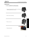
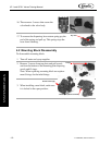
2.1 UF-1 and UFB-1 Valve Installation Procedure
1. Shut off syrup, unplug carbonator, shut off CO
2
and water supply to the unit.
2. Release pressure in lines by activating valves and lifting relief valve of carbonator
INSTALLATION